A block machine hydraulic station is often described as the source of pressure, but this description hides the way its components cooperate. The electric motor does not press the mould directly. The hydraulic pump does not create pressure independently of load. Valves do not generate power. Each component performs a different function within an energy chain that begins with electricity and ends as controlled force and movement at a cylinder.
Understanding this chain helps plant managers and buyers interpret machine specifications correctly. It also prevents common troubleshooting errors, such as replacing a pump when the motor voltage is unstable, increasing relief-valve pressure when a cylinder is mechanically blocked, or using higher-viscosity oil to hide internal leakage. This article explains how the motor, pump, valve group, oil circuit, and cylinders work together during concrete block production.
What the Hydraulic Station Does in a Block Machine
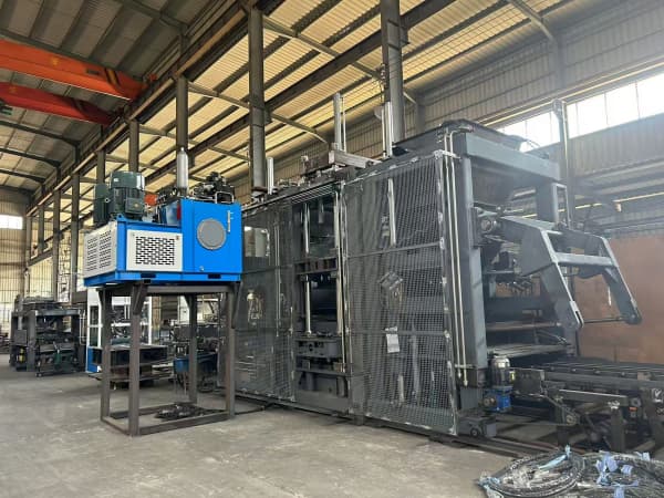
The hydraulic station supplies controlled oil flow to machine actuators. Depending on the machine design, hydraulic cylinders may move the material feeder, raise or lower the mould, position the tamper head, press the concrete, demould fresh products, clamp assemblies, or operate auxiliary equipment. Some movements require high speed with moderate force, while pressing or lifting may require higher force at a controlled speed.
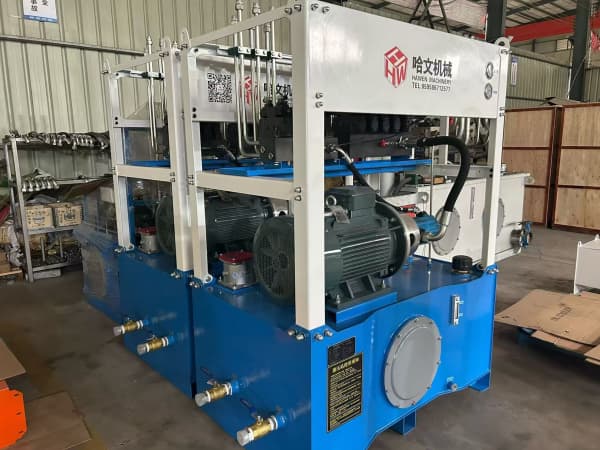
The station normally contains one or more electric motors, hydraulic pumps, an oil tank, suction and return lines, filters, directional and pressure-control valves, gauges or pressure sensors, temperature monitoring, a cooler where required, and connection ports leading to the machine. Accumulators may also be used in some designs to store hydraulic energy, absorb pulsation, or support peak flow.
A modern block making machine depends on repeatable timing as much as maximum force. The hydraulic circuit must respond consistently when the PLC commands each motion. A cylinder that reaches its endpoint late can delay the next vibration, feeding, or demoulding step. Small hydraulic instability can therefore appear as variable cycle time, product-height variation, mould impact, or an intermittent alarm.
Energy Path from Electric Motor to Hydraulic Cylinder
The electric motor converts electrical energy into rotary mechanical energy. Its shaft drives the hydraulic pump through a coupling or another specified connection. The motor must provide enough torque across the operating range and must tolerate starting, acceleration, continuous running, and pressure peaks without excessive current or temperature.
The pump draws oil from the tank through the suction path and displaces it into the pressure line. A pump primarily creates flow. Pressure rises when that flow meets resistance, such as the load on a cylinder, a restricted valve passage, or a relief-valve setting. If oil can return to tank with little resistance, system pressure remains relatively low even while the pump rotates.
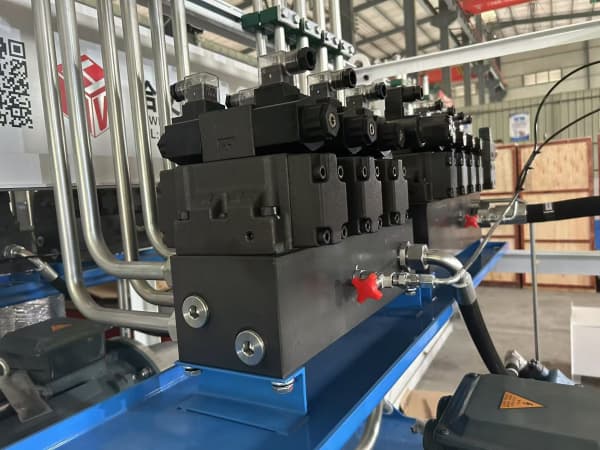
Directional valves route pressurized oil to one side of a cylinder and connect the opposite side to return. The pressure difference across the piston produces force, while delivered flow determines movement speed. When the valve reverses, the flow paths reverse and the cylinder changes direction. Proportional control can vary the valve opening according to an electrical command, allowing smoother acceleration, speed adjustment, or pressure control.
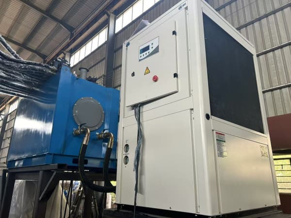
After doing useful work, oil returns through the circuit to the tank, often passing through a return filter and cooler. The tank is not only storage. It supports heat dissipation, air release, contamination settling, and a stable supply to the pump. Poor tank design, low oil level, or a restricted breather can affect the complete system.
The cylinder converts hydraulic energy back into linear mechanical work. The mould and tamper respond after losses in the motor, pump, valves, pipes, seals, and mechanical linkages are considered.
How Motor Power, Pump Flow, and System Pressure Relate
Three values are frequently confused: motor power, pump flow, and hydraulic pressure. Motor power is the rate at which mechanical energy can be supplied to the pump. Pump flow is the oil volume delivered per unit time. Pressure represents resistance to flow and, at a cylinder, contributes to available force.
Cylinder force is approximately pressure multiplied by effective piston area, before efficiency and friction losses. Cylinder speed is approximately flow divided by effective area. Increasing pressure can increase available force but does not automatically make the cylinder faster. Increasing pump flow can increase speed, but the motor and valves must handle the corresponding power and flow demand.
A useful theoretical relationship is hydraulic power equals pressure multiplied by flow, with unit conversion as required. Actual motor selection must also account for pump efficiency, drive efficiency, starting condition, duty cycle, service factor, and expected pressure peaks. A motor that appears adequate from nominal numbers may overload if the pump operates near maximum pressure for too much of the cycle.
Pump displacement and rotational speed establish theoretical flow. Actual flow is lower because internal leakage increases with wear, pressure, temperature, and oil condition. A worn pump may still produce acceptable no-load movement but lose speed or pressure capability under load. Testing should therefore compare pressure and flow under defined operating conditions.
A larger motor is not a universal improvement. If the pump displacement, valve passages, piping, cylinder area, and control logic remain unchanged, additional motor capacity may provide no production benefit. The correct design matches all components to the machine's motion and force requirements.
At standby, the motor may continue driving the pump while oil unloads at low pressure, or the drive may be controlled according to the system design. The circuit must avoid unnecessary high-pressure circulation because energy lost across restrictions becomes heat. Sensors confirm that the mould, tamper, feeder, and pallet are in safe starting positions.
During pallet positioning and feeding, cylinders move mechanisms at controlled speed. These actions generally need smooth acceleration and accurate endpoint detection. A sudden feeder movement can distribute concrete unevenly, while a mould or pallet movement that stops harshly can increase mechanical impact.
During forming, vibration mobilizes the dry-cast concrete while the tamper head descends. Hydraulic control determines tamper movement and pressing behavior, but vibration performs much of the particle rearrangement. The system should coordinate pressure and speed with the material condition and mould geometry. Maximum hydraulic pressure alone does not guarantee dense blocks.
At the compression or height-control stage, the circuit may transition from faster approach to slower controlled movement. Pressure rises as resistance increases. A proportional valve and PLC can manage this transition so the tamper reaches the required position without a damaging impact. The machine may use position, time, pressure, or a combination of signals depending on design.
During demoulding, the mould rises or the product is released according to the machine arrangement. Movement should be smooth enough to protect green block edges and webs. If the product sticks, increasing hydraulic force can conceal a moisture, mould-cleanliness, clearance, or alignment problem. The diagnostic sequence should identify mechanical resistance before pressure is raised.
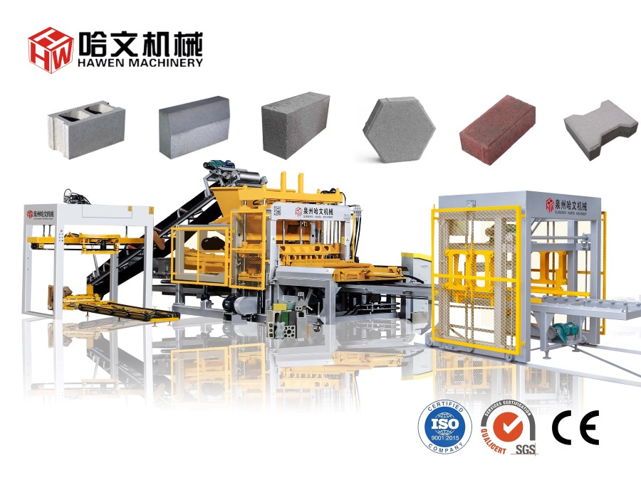
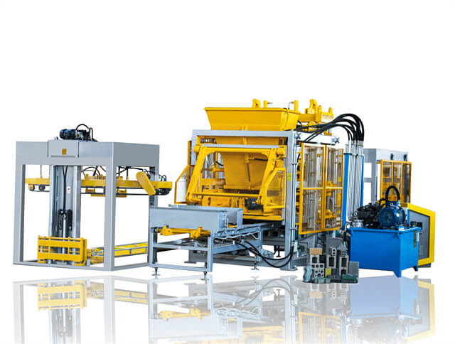
A medium-capacity system such as the QT6 cement paver brick production machine and larger machine platforms may use different pump groups, cylinder dimensions, valve capacities, and timing. Hydraulic requirements should therefore be compared by actual functions and cycle demand, not by one pressure figure.
Role of Directional, Proportional, and Relief Valves
A directional valve selects where oil flows. Its spool connects pressure, actuator, and return ports in specific combinations. Solenoids, pilots, springs, or proportional actuators move the spool. A sticky spool, weak electrical connection, contaminated pilot passage, or damaged seal can create delayed or incomplete movement.
A proportional valve adjusts flow or pressure continuously according to an electrical signal rather than operating only fully open or closed. This supports controlled speed ramps, repeatable pressure, and smoother transition between machine stages. Calibration must include both electrical command and hydraulic response; changing software parameters cannot correct a mechanically damaged valve.
The relief valve limits maximum system pressure by opening a path when pressure reaches its setting. It is a protection and control component, not a method for continually forcing a blocked machine. If the relief valve operates for long periods, energy becomes heat, oil temperature rises, and component life may decrease.
Check valves prevent reverse flow, while pressure-reducing, sequence, counterbalance, and flow-control valves may perform specialized functions. A circuit diagram is essential because two visually similar valve blocks can behave differently. Maintenance teams should trace symbols and port functions instead of adjusting every visible screw.
The PLC coordinates valve commands with sensors and motor control. The deeper relationship between digital commands and oil movement is explained in the site's overview of PLC control in modern block machines. For troubleshooting, always confirm whether the command was issued before concluding that a hydraulic component failed.
Oil Temperature, Filtration, and System Efficiency
Hydraulic oil transmits energy, lubricates components, carries heat, and transports contamination to filters. Its viscosity must remain suitable for pump lubrication and valve response. Oil that is too cold can increase suction resistance and sluggish movement. Oil that is too hot becomes thinner, increases internal leakage, reduces lubrication, and accelerates seal and oil degradation.
Heat comes from inefficiency. Common sources include prolonged relief flow, throttling across valves, internal leakage, undersized lines, excessive pressure settings, poor cooling, and repeated acceleration of heavy components. A cooler removes heat but should not be used to ignore the source of abnormal heat generation.
Contamination can damage pump surfaces, block small valve passages, scratch spools, and wear cylinder seals. New oil is not automatically clean enough for every system. Filling should use a controlled method, filters should match the required cleanliness and flow, and replacement intervals should reflect condition and manufacturer guidance.
Suction conditions are critical. A clogged suction strainer, collapsed hose, low tank level, air leak, unsuitable oil viscosity, or excessive pump speed can cause cavitation or aeration. Symptoms include whining noise, unstable pressure, vibration, foaming, and accelerated pump damage. The pump should not be replaced until the inlet condition is checked.
The detailed hydraulic station maintenance checklist provides a useful operational reference, but each factory should follow the machine manual and its actual duty conditions. Records of oil temperature, filter changes, pressure, motor current, and unusual noise make gradual deterioration easier to identify.
Practical Fault Diagnosis for Motors, Pumps, and Valves
| Observed symptom | Possible causes | First checks |
|---|
| Motor current is high and movement is slow | Mechanical blockage, excessive pressure, pump damage, cold oil, restricted line | Load condition, pressure gauge, oil temperature, coupling, return and suction restrictions |
| Pump is noisy and pressure fluctuates | Cavitation, air ingress, low oil level, clogged inlet, worn pump | Tank level, foam, suction hose, breather, oil viscosity, inlet filter |
| Cylinder moves normally unloaded but slows under load | Internal pump leakage, cylinder bypass, relief leakage, insufficient motor torque | Pressure-flow test, cylinder holding test, relief behavior, voltage and current |
| One action jerks while others are normal | Local valve, air in cylinder line, sensor timing, guide resistance, cylinder seal | Valve command, spool response, cylinder line, position signal, mechanical alignment |
| Oil temperature rises rapidly | Continuous relief flow, internal leakage, undersized cooler, restricted passages | Pressure during standby, cooler operation, leakage, valve position, filter indicator |
Diagnosis should follow the energy path. Confirm electrical supply, motor rotation, coupling condition, pump inlet, pump output, valve command, pressure at test points, cylinder response, and mechanical load. Changing several pressure and PLC parameters at once makes the result difficult to interpret and can introduce new risks.
For a general system comparison, the article on how hydraulic systems work in block machines identifies the principal station components. Factory technicians should combine that overview with the circuit diagram, manufacturer test values, and site measurements rather than diagnosing from sound or pressure alone.
Frequently Asked Questions
Does the hydraulic pump create pressure or flow?
The pump primarily creates flow. Pressure develops when the flow meets resistance from a load or control component. The circuit and relief setting limit how high pressure can rise.
Will a larger hydraulic motor make the block machine faster?
Not by itself. Speed depends mainly on pump flow, cylinder area, valve and line capacity, and control timing. Motor power must support the required pressure and flow but does not independently determine actuator speed.
Why does the pump become noisy after the machine warms up?
Possible causes include low oil level, air ingress, restricted suction, deteriorated oil, internal wear, or temperature-related leakage. Check inlet conditions and oil state before replacing the pump.
Should hydraulic pressure be increased when blocks are not dense enough?
Not automatically. Density also depends on mixture grading and moisture, mould filling, vibration, tamper position, and cycle timing. Increasing pressure without diagnosis can increase wear without correcting the cause.
Why can one hydraulic movement be slow while others remain normal?
A local valve, cylinder seal, hose restriction, sensor command, or mechanical guide may be responsible. If all movements are slow, investigate the shared motor, pump, oil, and main pressure circuit first.
Conclusion
The block machine hydraulic station works through a connected energy path. The electric motor supplies rotary power, the pump produces oil flow, valves control direction, pressure, and speed, and cylinders convert hydraulic energy into machine movement and force. Pressure appears in response to resistance; it is not an isolated output that guarantees product quality.
Reliable operation depends on correctly matching motor power, pump displacement, operating pressure, valve capacity, cylinder area, piping, oil viscosity, cooling, filtration, sensors, and PLC timing. When faults occur, tracing this sequence is more effective than immediately raising pressure or replacing the pump. A balanced hydraulic system supports smooth feeding, controlled pressing, clean demoulding, repeatable cycle time, and consistent concrete products.





 Tel: +86-13905968794
 Email: export@hwmachines.com
 MP/WhatsApp: +86-13905968794
 Manufacturer Address:Nanan,Quanzhou City,Fujian Province,China