Insulation inserts placed in concrete masonry cores can affect more than the wall's energy calculation. Their shape must fit the unit, leave required grout cells clear, and work with reinforcement and the wall's installation sequence. This article focuses on specification and manufacturing coordination, so the unit, insert, and structural detail arrive as a compatible package.
Thermal performance belongs to the complete assembly, not to a foam insert in isolation. CMHA's TEK 06-11A explains how unit geometry, insulation location, finishes, density, and grouted cores affect the wall. The manufacturer can control unit dimensions and consistency, while the designer confirms thermal values, code compliance, and structural requirements.
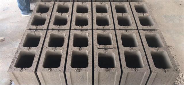
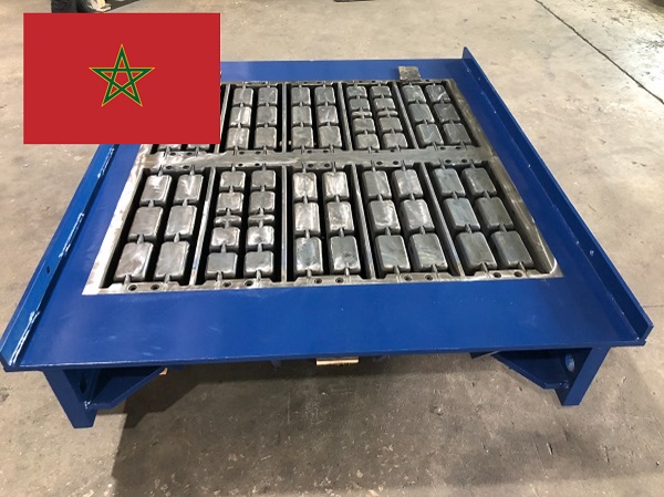
Unit core geometry is the interface that the insert and structural design must respect.
1. Define what the insert must do
Start by identifying whether insulation is placed in selected cores, throughout ungrouted cores, or in a purpose-designed unit configuration. Confirm the target wall assembly, climate and code basis, fire and moisture considerations, and whether the masonry is partially or fully grouted. Those decisions determine which cells remain available for insulation and which must receive reinforcement or grout. A supplier should not infer the layout from a generic block size or a product photograph.
Specify the insert's material, shape, retention method, coverage, and installation sequence. Some inserts have slots or cutouts that accommodate reinforcing bars and grout in a designed cell. Others occupy only ungrouted cores. The drawing should show the insert in section with the actual concrete unit, webs, bars, grout, mortar, and finishes. This avoids a late field conflict where insulation is trimmed away or a structural cell is unintentionally obstructed.
2. Coordinate heat flow with reinforcement and grout
A wall's thermal response depends on more than nominal insulation thickness. Concrete webs, grouted cells, mortar joints, finishes, and the location of insulation all contribute. CMHA notes that the unit type and density, insulation placement, and grouting schedule influence steady-state and thermal-mass behavior. Use project-specific assembly calculations or approved data instead of assigning the insert's advertised resistance directly to the whole wall. The design professional should verify the method against the applicable energy requirements.
The insert must preserve the clear dimensions required for reinforced cells and grout placement. Check bar size, cover, lap positions, grout path, and any cleanout or inspection access against the current structural details. Inserts should not bridge across a cell that must be filled, shift reinforcement, or prevent grout consolidation. Where a combined insert-and-reinforcement cell is proposed, obtain supporting product and design details and confirm them with the responsible engineer before production begins.
Consistent webs and cores help inserts seat as intended from unit to unit.
3. Match the insert to the actual unit profile
Measure the concrete masonry unit's core width, depth, web location, and dimensional variation before finalizing an insert. An insert that is too loose can fall or rotate during laying; one that is too tight can deform, damage a web, or slow installation. Check how the insert meets the mortar bed and whether a cut or notch creates a gap that changes the intended coverage. Review several production units rather than designing around a single hand-selected sample.
Confirm the insert can be installed in the intended direction and can be identified by course or wall location. For projects with multiple unit widths or reinforcement patterns, list a distinct insert designation for each configuration. Keep the unit, insert, and installation drawings on the same revision. If the contractor needs field trimming, define where it is allowed and what must remain intact; uncontrolled cutting can create inconsistent voids and complicate inspection.
Receiving inspection should check the insert's profile, edges, slots, and identification against its approved submittal. Look for crushed corners, warped sections, contamination, or damage that could prevent seating. Store components so they remain clean and protected from handling damage, and keep lot labels attached until they are issued to the work area. These checks do not require a new engineering test; they make sure the supplied component is the one that was reviewed and that field crews can select the right piece.
A practical fit trial should include ordinary units, corner conditions, and at least one location where reinforcement or a service penetration changes the available space. Ask the installer to place and remove the insert using the intended sequence, then check whether it stays seated during normal unit handling. Record any trimming, orientation marks, or adjustments that are accepted. The trial converts a cross-section into a buildable instruction and reveals access problems while the supplier can still revise the component schedule.
The submittal schedule should identify the insert manufacturer, series, product code, drawing revision, compatible unit family, and orientation where relevant. If a project combines several unit widths, list each pairing explicitly instead of using a broad note such as fits standard block. At delivery, compare carton or bundle labels with the approved schedule and keep different profiles separated. Any substitution should be reviewed against the same fit and reinforcement details before installation, then recorded so a later inspection can identify what was actually supplied.
4. Select compatible concrete units and production tooling
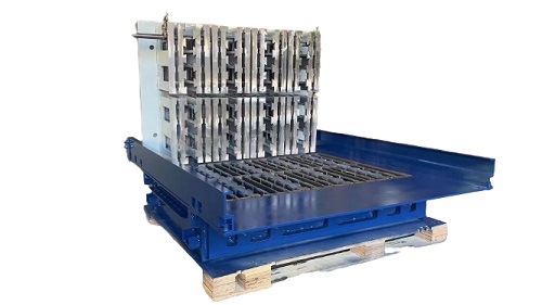
The insert specification should identify the block profile and manufacturing tolerance needed for repeatable seating. If a special core shape or web arrangement is required, confirm that the mold and machine can produce it without reducing the unit's required face-shell or web dimensions. Hawen Machinery can review a hollow block mold, concrete block mold, or mold catalog against the released drawing. Hawen molds are designed for compatibility with Masa, Hess, Zenith, Poyatos, Besser, Tiger, Columbia, Quadra, and Omag platforms; heat treatment improves wear resistance, with hardness tested at HRC 59-61.
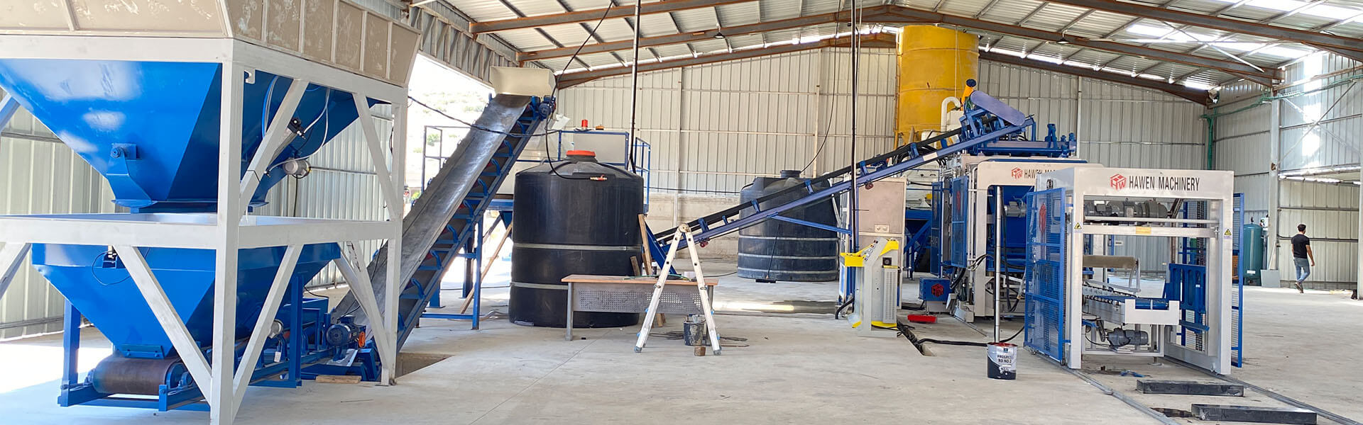
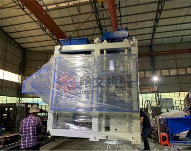
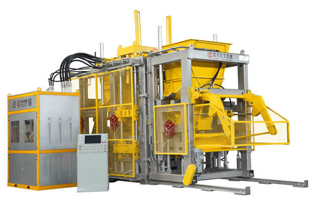
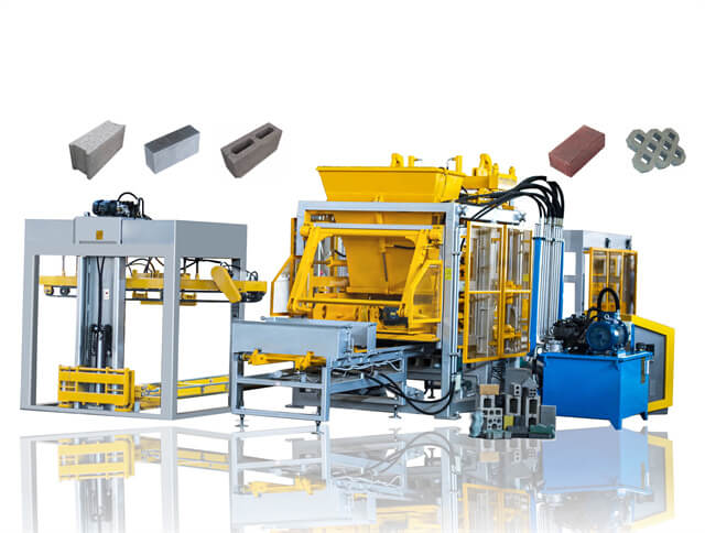
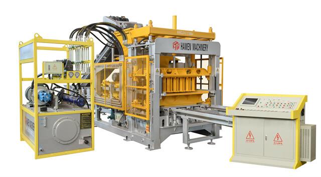
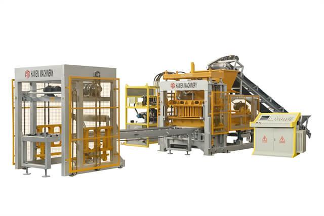
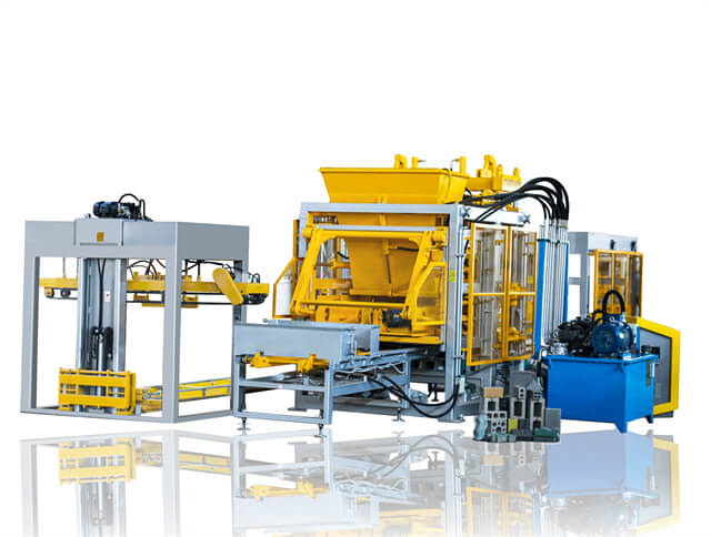
For production planning, compare a QT12 hollow-block line or QT10 block machine with the required mold footprint, pallet, curing arrangement, and output mix. The objective is stable unit geometry, not simply the fastest press cycle. If inserts are supplied separately, include receiving inspection and a trial installation in the pre-production approval so fit issues are resolved before a full order is released.
Machine and tooling selection should follow the released unit specification.
5. Control production and inspection for insert fit
At trial production, sample units from different mold cavities and measure the dimensions that control insert seating. Record core size, web position, overall dimensions, and visible damage. Place the insert into representative units using the same method planned for the job. Check that it stays in position during lifting and laying, that it does not obstruct grout cells, and that installers can distinguish the required orientation. Document any adjustment to the unit or insert drawing before approval.
During routine production, use cavity-based checks to detect wear or drift. If an insert fits one cavity but not another, compare the core dimensions and mold condition. If fit changes across an entire run, review process setup, material consistency, pallet condition, and inspection records. Hawen's four-shaft vibration box positions eccentric blocks outside its housing, reducing internal resistance and supporting uniform compaction. This helps the process form consistently, but dimensional checks remain necessary for the insert interface.
6. Plan installation, moisture, and durability details
Clarify how inserts are stored, protected from damage, and delivered to each work area. If they are installed as the wall is laid, specify how the crew will keep uninsulated grout cells clear. If installation happens later, confirm access and retention. Coordinate cuts around corners, openings, bond beams, lintels, and service penetrations. The detail should also address how the selected insulation strategy interacts with flashing, drainage, air control, and vapor management for the specific climate and assembly.
Do not treat core insulation as a substitute for moisture detailing or workmanship. CMHA's guidance on insulating concrete masonry discusses the wall as a system, including insulation location, grouted cells, and finishes. Confirm the design's fire provisions and any required testing or approvals for the insert material. A sample wall section can reveal practical conflicts before construction, especially where reinforcement and insulation share limited core space. Record the approved procedure so each crew follows the same sequence.
7. Plan Hawen Machinery's production scope
Hawen Machinery can assess the specified unit, insert fit, mold, board, curing flow, and line capacity together. Relevant equipment may include a QT15 automatic block machine, QT8 brick machine, batching system, concrete mixer, and production pallets. Share the unit drawing, insert section, local standards, daily product demand, and utility conditions so the proposal is based on the actual product rather than a generic equipment list.
A SIEMENS S7-200 PLC with a touch panel and remote monitoring can help operators review machine status and production parameters. Also consider automatic pallet supply, offline palletizing, and the block machine range as part of the material flow. Hawen can help with manufacturing and equipment coordination, while the project's architect and engineer retain responsibility for assembly thermal performance, code approval, reinforcement, and construction details.
Action checklist
Define the insulation location and identify every cell reserved for reinforcement or grout.
Show the insert, unit webs, bars, grout, mortar, and finishes together in a coordinated section.
Measure actual core geometry and test insert seating in units from multiple mold cavities.
Confirm installation direction, retention, field-cutting limits, moisture detailing, and fire requirements.
Use assembly-level thermal data and project code review rather than the insert rating alone.
Release unit, insert, mold, and installation instructions under coordinated revision control.
An insulation insert performs only when it belongs to a well-designed wall and fits the masonry unit consistently. Coordinate thermal modeling, reinforcing cells, grout access, product geometry, and installation details before production; then confirm that interface with representative samples. That disciplined handoff gives the project team a wall system that can be built as designed, not merely an insert that appears to fit on a drawing.
FAQ
Can every hollow concrete block core be filled with insulation? No. Some cores may be reserved for reinforcement, grout, services, or other design requirements. Follow the coordinated wall drawings.
Does the insert's R-value equal the wall's R-value? No. Webs, grouted cells, mortar, finishes, and insulation placement affect the thermal performance of the complete assembly.
Can an insulation insert share a core with reinforcing steel? Some products are designed for that arrangement, but the clear grout space and structural detail must be verified for the specific system.
What should be measured before choosing an insert? Check the actual core dimensions, web positions, unit tolerances, and any clearance needed for reinforcement and grout.
Should inserts be installed at the factory or on site? That depends on the product and construction sequence. Specify the method that protects the insert and preserves access to required grout cells.
Does core insulation eliminate thermal bridging? It may reduce heat flow through selected cores, but the wall assembly still includes concrete webs, joints, grouted cells, and other paths.
Who approves the insulation and structural compatibility? The responsible design professionals confirm assembly performance, code compliance, and reinforcement details; manufacturers provide product and dimensional information.





 Tel: +86-13905968794
 Email: export@hwmachines.com
 MP/WhatsApp: +86-13905968794
 Manufacturer Address:Nanan,Quanzhou City,Fujian Province,China