Where to Place Control Joints in Concrete Masonry Walls: A Practical Guide is a practical topic for buyers and plant managers who want a more stable block making machine workflow. The goal is not only to explain the issue, but to give a clear method that supports better output, cleaner operation, and stronger customer confidence.
In a professional concrete products factory, the block machine, material system, mold, pallet circulation, control system, and operator routine must work as one process. A good solution therefore looks at the whole line before changing one visible setting.
Product dimensions and documented shrinkage properties support the design discussion, but do not determine joint locations by themselves.
1. Understand the purpose of a control joint
A control joint is a planned vertical plane that divides a concrete masonry wall into panels so longitudinal movement can occur at a selected location. It is intended to reduce restraint and help manage shrinkage-related cracking. The joint is not simply a visible line in the mortar, and it is not automatically a structural separation. Its geometry, reinforcement, sealant, and effect on load paths must match the wall design and project documents.
Control joints are one part of a crack-control strategy. Designers may also use horizontal reinforcement, reinforced relief joints, or engineered analysis, depending on wall function and project conditions. Some walls may not need conventional control joints when reinforcement and structural design address movement differently. The engineer must decide which strategy applies. A construction crew should not add or omit a joint based only on a generic spacing rule or a neighboring building's detail.
2. Identify the movements and restraints
Concrete masonry can change volume as moisture content and temperature change, and it can experience long-term carbonation-related shrinkage. These effects alone do not explain every crack. A wall may also be restrained by foundations, roof or floor diaphragms, intersecting walls, returns, columns, lintels, or adjacent construction. Beam deflection, foundation settlement, construction sequence, and differential movement can create additional stress. Diagnosis should consider the whole assembly rather than blaming the block or mortar immediately.
Before setting out joint locations, collect the wall elevations, structural role, openings, support conditions, exposure, reinforcement, unit properties, and construction sequence. Ask whether the wall is load-bearing, part of a shear system, veneer, partition, or freestanding element. The movement strategy for one type cannot be copied blindly to another. CMHA Tech Note CMU-TEC-009-25 separates empirical, engineered, and reinforced-relief approaches because wall conditions and required performance vary; apply it with the locally adopted masonry design standard.
Stable geometry is one part of wall quality; movement detailing remains a design responsibility.
3. Map likely stress concentrations
Begin with the drawing and mark changes in wall height, thickness, stiffness, or support. Review locations above foundation movement joints and near floor or roof transitions. Re-entrant corners, wall intersections, and long uninterrupted elevations can create restraint patterns that deserve attention. Openings are also important: a joint may be considered near a jamb or between closely spaced openings, but its position can affect the load carried by the lintel and the continuity of reinforcement.
Control-joint placement should be coordinated with architectural lines, flashing, sealant continuity, fire and acoustic requirements, and interior finishes. A joint that is structurally convenient but conflicts with a door frame, facade module, or water-management detail can create a field problem. Mark the intended joint on every relevant elevation and section, then coordinate its construction detail with structural and envelope drawings. A written schedule is clearer than relying on a general note alone.
4. Select a spacing method instead of guessing
Empirical criteria in a recognized masonry guide provide a starting framework for common wall configurations. They relate joint spacing and horizontal reinforcement to wall geometry and material assumptions. An engineered approach can account for unit shrinkage and other inputs when the project is unusual or product data are available. Reinforced relief joints may be appropriate in some reinforced walls. The designer should choose the method and document the assumptions, rather than combining convenient pieces from different methods.
Do not treat a familiar distance such as twenty feet as a universal requirement. Applicable criteria may depend on panel proportions, reinforcement, openings, wall height, unit shrinkage, climate, restraint, and local code editions. Verify the current CMHA or project reference and the governing masonry design standard. If the project's conditions fall outside the tabulated assumptions, ask the engineer to evaluate them rather than extending a prescriptive table beyond its stated use.
Traceable production and curing records help engineers assess unit properties when needed.
5. Coordinate joints with openings and structural behavior
An opening interrupts the masonry panel and concentrates stress at its corners. A joint near a jamb may help isolate movement, but it can also change lintel action or divide a wall line that was intended to act continuously. Review the lintel span, bearing, reinforcement, bond beams, adjacent piers, and loads above. Do not locate a joint at a lintel end without checking whether the lintel was designed to carry the wall and superimposed loads without arching action.
Shear walls need particular care because a control joint may divide the wall into separate resisting panels. The engineer should verify the in-plane load path, reinforcement continuity, collectors, and connection to diaphragms. Similarly, a joint near a corner or intersection can change restraint and load transfer. Architectural preference should be coordinated with structural requirements early, before the blockwork layout, reinforcing schedule, and sealant details are issued for construction.
6. Detail the joint, sealant, and reinforcement correctly
A common control-joint detail creates a bond break through the vertical mortar joint and uses a backer material and sealant to maintain weather resistance while accommodating movement. The exact configuration depends on exposure, joint width, sealant manufacturer requirements, fire or acoustic rating, and the wall system. The sealant must be compatible with the substrate and joint design. Poor depth, inadequate surface preparation, or three-sided adhesion can shorten service life even when the joint location was sound.
Horizontal reinforcement is typically interrupted or specifically detailed at a control joint to avoid unintentionally restraining movement, unless the structural design requires a load-transfer detail. Never cut or discontinue reinforcing based on a field assumption. The structural drawings must show whether reinforcement stops, continues, or uses a sleeve or other engineered connection. Check bond beams, vertical bars, grout, and joint accessories together so a movement detail does not compromise required strength or stability.
7. Connect crack-control design with unit production
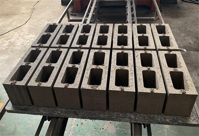
Unit properties are inputs to some crack-control approaches. Moisture condition at installation, aggregate behavior, cementitious content, curing, and drying shrinkage can influence movement potential. Designers may request ASTM C426 test data or other information under the governing specification. The producer should provide traceable product and lot records, not a generic value from a different mix or unit family. Testing, conditioning, and interpretation must follow the applicable standard and the engineer's instructions.
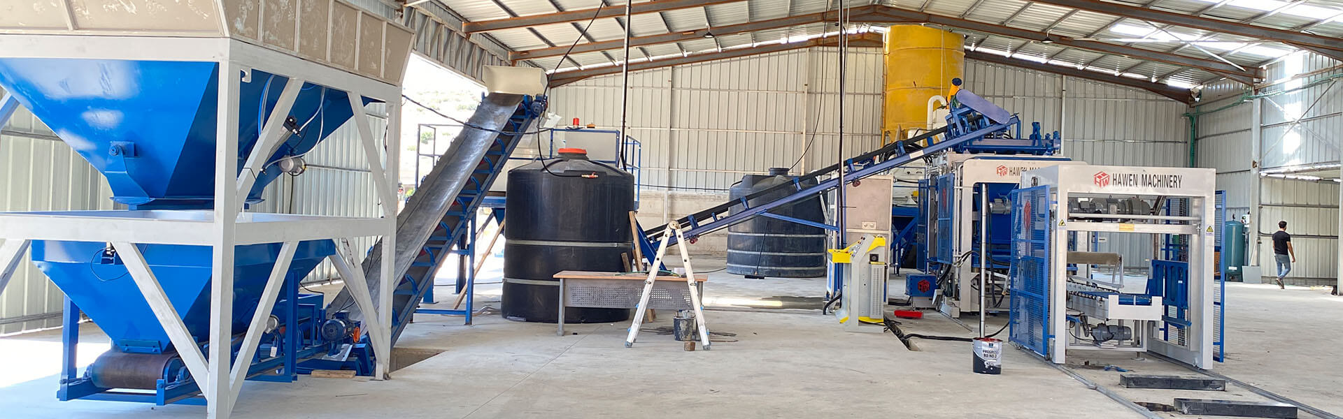
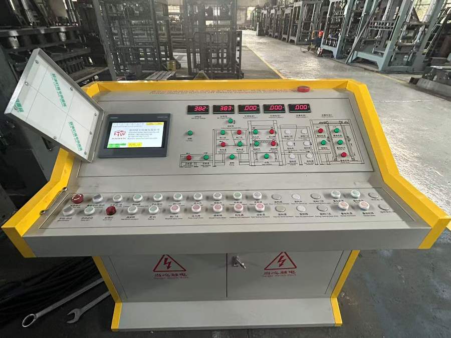
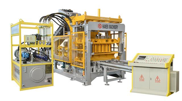
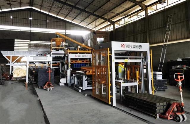
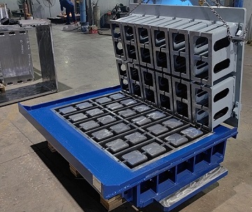
Hawen Machinery can discuss production consistency for the specified unit family. Its molds are designed to fit leading machine brands such as Masa, Hess, Zenith, Poyatos, Besser, Tiger, Columbia, Quadra, and Omag, following original interface specifications; heat treatment supports wear resistance, with hardness tested at HRC59-61. A four-shaft vibration-box layout places eccentric blocks outside the housing to reduce resistance and promote even compaction. A SIEMENS S7-200 PLC and touch panel with remote monitoring can help retain operating-status context for production review.
8. Inspect cracks before prescribing a repair
When a crack appears, record its location, direction, width, length, date, weather, wall age, nearby joints, openings, supports, and recent construction or temperature events. Photograph it with a scale and compare the observation over time. A crack near an omitted joint suggests one possible cause, not proof. Diagonal cracking, stair-step patterns, separation at supports, water entry, or changes in alignment may require prompt review by the responsible engineer.
Do not fill a moving crack with sealant until its cause and movement are understood. First check drawings, reinforcement, unit test records, mortar, foundation movement, lintel details, and the control-joint schedule. The engineer can determine whether the issue is cosmetic, related to restrained movement, or a structural concern, then specify repair or monitoring. Record any approved change so similar wall areas are not altered by an improvised site-wide rule.
Action checklist
Confirm the wall's structural role, support conditions, openings, reinforcement, exposure, and applicable design standard.
Map changes in height, thickness, stiffness, corners, intersections, foundation joints, and opening stress zones.
Use a stated empirical or engineered method; do not apply a generic spacing number without checking its assumptions.
Coordinate control joints with lintels, shear-wall action, reinforcement, sealants, flashing, and architectural details.
Use traceable unit-property data when the design method requires shrinkage or other product inputs.
Document crack location and movement before selecting a repair or changing the joint layout.
A control joint is most effective when it is designed into the wall rather than added after cracking begins. Map restraint, openings, supports, reinforcement, and exposure; select a recognized design method; and coordinate the joint through the structural and envelope details. With traceable unit information and disciplined field inspection, teams can manage movement deliberately while preserving the wall's intended load path and weather performance.
FAQ
Do all concrete block walls need control joints? No. The need depends on the wall design, reinforcement, geometry, restraint, exposure, and selected crack-control strategy.
How far apart should control joints be in a CMU wall? There is no universal spacing. Follow the applicable design method and have the engineer account for wall proportions, reinforcement, unit properties, and project conditions.
Where are control joints commonly considered? Designers review wall-height or thickness changes, supports, corners, intersections, and areas near openings, then verify structural and envelope effects.
Can I place a control joint at the end of a lintel? Only after the engineer checks lintel load transfer and arching assumptions; the joint may change how the wall above is supported.
Should reinforcement continue through a control joint? Follow the structural detail. Reinforcement may be interrupted to permit movement or specifically detailed to transfer load; do not decide in the field.
What is the difference between a control joint and an expansion joint? Concrete masonry commonly uses control joints to accommodate shrinkage-related movement; clay masonry often uses expansion joints for its different movement behavior.
Can a block manufacturer choose the control-joint locations? No. The manufacturer can provide specified unit data, but joint location and wall behavior are design decisions for the responsible professional.





 Tel: +86-13905968794
 Email: export@hwmachines.com
 MP/WhatsApp: +86-13905968794
 Manufacturer Address:Nanan,Quanzhou City,Fujian Province,China