Block Mould Changeover: Alignment Checks That Prevent Early Wear and Defective Units
A block machine may change from hollow blocks to paving stones several times during a production month. The change looks straightforward: remove one mould, install another and select a new recipe. In practice, the connection between mould box, tamper head, mounting frame, feeding device and pallet support determines whether the new tooling runs correctly. A mould that fits the nominal machine model can still be damaged if its interfaces are not checked during installation.
This article is a workshop guide for the moment a plant changes moulds. It focuses on alignment, clearances and a controlled first run. Those checks protect both the tooling and the machine, and they help operators distinguish installation problems from mix or vibration problems. Exact tolerances and fastener requirements must come from the machine and mould drawings; the checks below are a framework rather than a substitute for manufacturer instructions.
Why Changeover Deserves a Procedure
The mould box shapes the outside of the product and supports its internal cores. The tamper head enters the cavities and compacts material while the machine applies vibration and pressure. Both move in a constrained space. A small horizontal offset may cause a tamper shoe to touch a mould wall, scrape a core or load a guide unevenly. A small height error may leave blocks undercompacted or cause unwanted contact at the bottom of the stroke.
Production symptoms can be delayed. A poorly installed mould may produce acceptable blocks for a short period while its contact surfaces polish or wear. After longer operation, the plant sees chipped edges, uneven height or metal particles near the cavity. Treat unusual noise, bright contact marks and changes in motor load as reasons to stop and inspect. Continuing at full speed can convert a correctable setup issue into damage to both the mould and the machine.
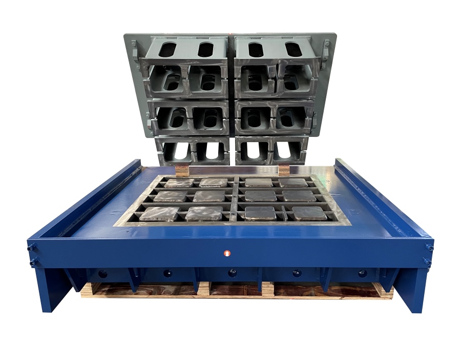
The process should be especially careful when a mould is purchased from a different supplier. Sharing a model name does not establish that the mounting pattern, reference surfaces and height stack match the actual machine. Before buying replacement tooling, provide the supplier with drawings or measured dimensions, product drawings, pallet size, tamper connection details and clear photos. The concrete block mould range shows how different product families require different geometry; interchangeability must be verified at the interface level.
Checks Before Removing the Old Mould
Record the machine state while the existing mould is still running well. Save the product recipe, filling time, vibration profile, tamper position, demoulding behavior, typical block height and cycle time. Photograph the mounting points and cable or hose routing. Mark the mould orientation so it cannot be reversed accidentally in storage. These records give the team a reference when the new mould runs differently.
Plan lifting before loosening any fasteners. Obtain the mould assembly weight and center of gravity, confirm that lifting eyes and slings are rated, and clear the movement path. Follow the machine's lockout and stored-energy procedure for electrical, hydraulic and pneumatic circuits. A raised tamper or feeder can move unexpectedly when pressure is released; secure moving parts as the manufacturer instructs. Clean loose concrete from the machine before lifting so debris cannot fall into guides or onto reference faces.
Inspect the old mould as it comes out. Wear marks can reveal the machine's condition. Similar wear on all sides suggests normal service, while one-sided scoring may point to a guide or alignment fault. A new mould should not be asked to absorb an existing misalignment. Check guide rails, bushings, pallet support and tamper travel before installing it. If the machine itself has a defect, correct that first.
Verify Machine and Mould Interfaces
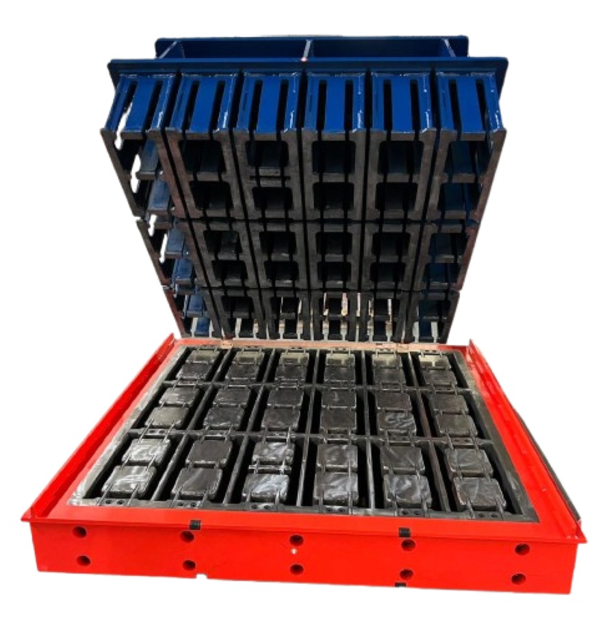
Compare the delivered tooling with approved drawings and the actual machine. Check the mould box envelope, mounting hole locations, reference faces, lifting points, cavity orientation and clearance to the feeding cart. Verify the tamper head connection, shoe pattern, penetration depth and space around cores. Confirm that the required pallet width and length match the plant's pallet supply. The support condition below the mould is as important as the upper mounting connection.
Dimensions on a sales sheet are not enough to confirm fit. Measure the machine's relevant datums and the delivered assembly, using the same references stated on the drawings. A dimension measured from the outer edge of a bracket cannot be compared with one measured from a machined centerline. If the references differ, obtain a clarification from the tooling supplier before installation. Never enlarge holes or grind a mating surface simply to make a new mould enter the frame without engineering approval.
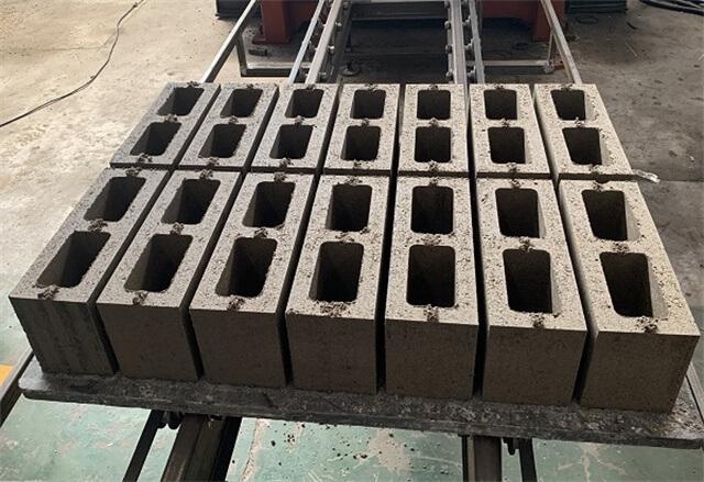
Inspect the mould's condition after transport. Look for damaged corners, bent mounting tabs, loose fasteners, coating on mating surfaces and trapped packing material. A high spot or hardened concrete residue under a mounting foot can tilt the entire assembly. Clean and inspect both mating faces, then verify that the mould seats evenly before tightening. For hollow block moulds, inspect cores and thin webs particularly closely because minor contact damage can affect several cavities at once.
Installation and Alignment
Position the mould using the specified lifting points and a controlled hoist movement. Seat it on its reference surfaces without using mounting bolts to pull a misaligned assembly into place. Install the correct fasteners and tighten them in the sequence and torque stated by the manufacturer. If dowels, keys or locating blocks are fitted, ensure they engage properly. Missing location features can let the mould shift during vibration even when bolts initially feel tight.
Bring the tamper toward the mould slowly under the approved service procedure. Confirm uniform clearance around the perimeter and internal cores. Rotate or move the mechanism only in the manner permitted by the machine manufacturer. Check at several stroke positions, since a tamper can appear centered at the top but move off center near the working position if a guide is worn. Verify that the bottom position gives the intended product height without metal-to-metal contact.
Check the pallet path as well. A pallet must enter squarely, support the moulded product and leave without dragging an edge. Poor pallet positioning may be misread as a mould problem. If the plant uses an automatic pallet provider, test several empty pallets, including examples at the accepted thickness limits. Check that the feeding cart clears the mould and distributes material over the full cavity field rather than striking projecting components.
Any adjustment to guide position, tamper travel or feeder height should be documented as a machine setting. Avoid correcting a physical interference with a recipe change. Slower vibration or more water can hide incomplete filling for a few cycles, but it does not remove the interference that causes wear. Keep mechanical checks and mix optimization as separate steps during commissioning.
Dry Run and First Concrete Trial
Begin with a dry run at a safe reduced speed if the machine permits it. Observe the full motion of the feeder, tamper, mould and pallet transport. Listen for contact and inspect for fresh polished marks after several cycles. Where practical, use a temporary witness material or the manufacturer-approved clearance method to confirm near-contact areas. Do not put hands inside the operating envelope during movement.
Then run a small concrete trial. Start from the documented recipe for that product family, but expect to adjust filling time and vibration because cavity volume and geometry have changed. Inspect units from every cavity. Measure height at consistent points, look for corner damage, underfilled ribs and variations across the pallet. Weigh sample units and compare their spread, not only their average. An even average can hide one cavity that is repeatedly underfilled.
Allow enough cycles for the mixer and feeder to reach steady conditions. Inspect the mould after the first limited run, and repeat the check after an initial production interval. Vibration can loosen a fastener that was not properly seated or reveal a contact point that was not obvious during a manual check. Only then increase to normal speed. Product acceptance still requires the applicable dimensional and strength tests after curing; fresh shape is an early process check, not final proof of quality.
| Stage | Primary check | Reason |
|---|
| Before installation | Drawings, datums and transport condition | Confirm actual machine compatibility |
| After seating | Reference faces and locating features | Avoid tilted or shifting tooling |
| Dry run | Tamper, feeder and pallet clearance | Find interference before full vibration |
| Concrete trial | Every cavity, block height and mass | Confirm filling and forming uniformity |
Records and Maintenance
Keep a changeover sheet for each mould. Include the tooling serial number, product drawing revision, machine number, installation date, lifting method, fastener record, initial clearances, setup parameters and first-run observations. Photograph both acceptable products and any defect. These records make future changeovers faster and allow a supplier to diagnose a genuine tooling issue without guessing how the mould was installed.
Store removed tooling on proper supports. Protect machined faces and cores from impact and corrosion, and avoid resting the mould on delicate product-forming edges. Clean concrete from accessible areas by the approved method, without damaging surface treatments. Inspect wear before storage so the next production run does not begin with a repair surprise. For plants making several product families, label associated tamper heads and mould boxes as matched sets.
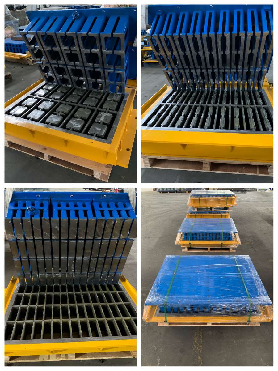
Establish an inspection interval based on production cycles and observed wear rather than a calendar date alone. Check fasteners, contact marks, guide condition, product dimensions and surface finish. Where an outside supplier provides the tooling, share measured evidence with them before modifying it. The mould project examples can help frame compatibility discussions, but the machine's own drawings remain the decisive source for installation dimensions.
FAQ
Can two moulds for the same block machine model be exchanged without adjustment? Not necessarily. Confirm the delivered assembly's mounting datums, tamper connection and working height against the actual machine before running.
What is the first sign of tamper and mould interference? Fresh scoring, unusual noise, uneven product edges or a shift in drive load can be early signs. Stop and inspect rather than waiting for a visible failure.
Should a new mould be tested at normal production speed immediately? Begin with the manufacturer's approved slow or service procedure, then a limited concrete trial and inspection before increasing to normal speed.
What information helps a supplier resolve a fit problem? Provide machine and mould drawings, measured datums, photos of mounting and contact points, the tooling serial number and a description of when the problem occurs.
Conclusion
A mould change is a precision setup task. Confirm interfaces, seat the tooling on clean reference surfaces, verify moving clearances and inspect every cavity during the first production trial. A short, documented changeover procedure protects the mould investment and makes product quality more repeatable.





 Tel: +86-13905968794
 Email: export@hwmachines.com
 MP/WhatsApp: +86-13905968794
 Manufacturer Address:Nanan,Quanzhou City,Fujian Province,China