A production line can fit inside a factory building and still be difficult to maintain. The forming machine may have enough room to operate, while a mould cannot be removed along the planned route. A mixer may be positioned efficiently for material delivery, but its inspection opening may face an obstruction. An electrical cabinet may stand beside a clear walkway until its door is opened for authorized servicing.
These problems arise when layout reviews consider only the equipment footprint and normal production flow. Maintenance also requires access for inspection, cleaning, component removal, handling equipment, and the people carrying out authorized work. Some of that space is needed continuously, while other areas become active only during a planned shutdown. Buyers should identify both before approving the equipment arrangement.
This guide explains how to review maintenance access around a concrete block, paver, or kerbstone production line. It does not prescribe a universal clearance or a lifting procedure. Dimensions and work methods must be confirmed for the supplied equipment, the building, applicable requirements, and the factory's operating procedures. The purchasing objective is an arrangement in which service tasks can be planned and completed without unanticipated obstructions.
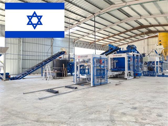
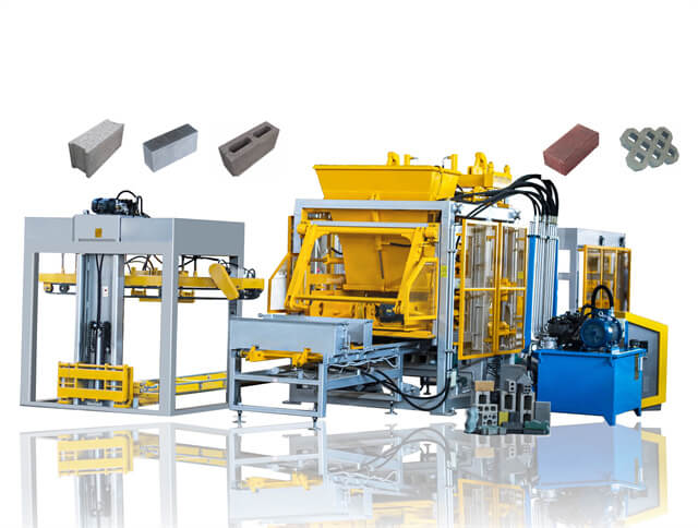
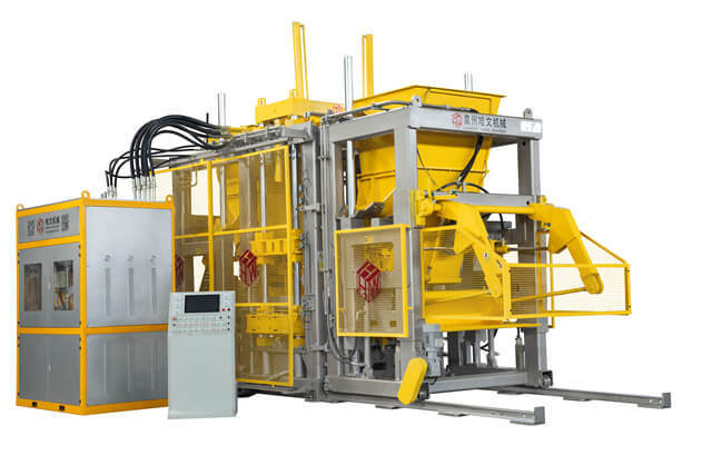
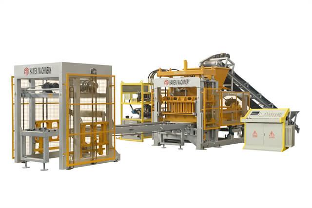
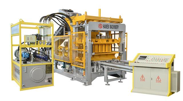
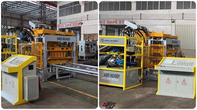
A customer-site photograph illustrates an equipment arrangement; it cannot establish the service clearances required for another project.
Distinguish Operating Footprints from Service Envelopes
Ask the supplier to distinguish the stationary equipment outline from the areas required for operation and service. An operating footprint describes where the installed equipment stands. A service envelope includes the space needed when a door, guard, cover, drawer, or removable component is moved into its maintenance position. Those boundaries may extend beyond the outline shown on a simple sales drawing.
Identify the tasks that determine each service envelope. Routine inspection may need access to a small observation point, while replacing a drive component or removing a mould may require a much larger route. The layout should show the relevant movement and destination rather than a general note saying leave maintenance space. Buyers need to understand which tasks the supplier has considered and which still require site planning.
Separate permanent clear areas from areas that may be reserved during planned work. A permanent access point should not become a storage position between maintenance events. A temporary work area can sometimes share space with another activity, but the factory must know how it will be made available. Record the condition for sharing it and the person responsible for clearing it before work begins.
Include the building and other installed services in the review. Columns, walls, cable routes, piping, doors, stairs, and neighboring equipment can limit movement even when the floor appears open. Check height as well as floor area where components or handling equipment move vertically. A two-dimensional footprint is a useful starting point, but it may not reveal all obstructions.
Plan Mould Removal and Replacement Routes
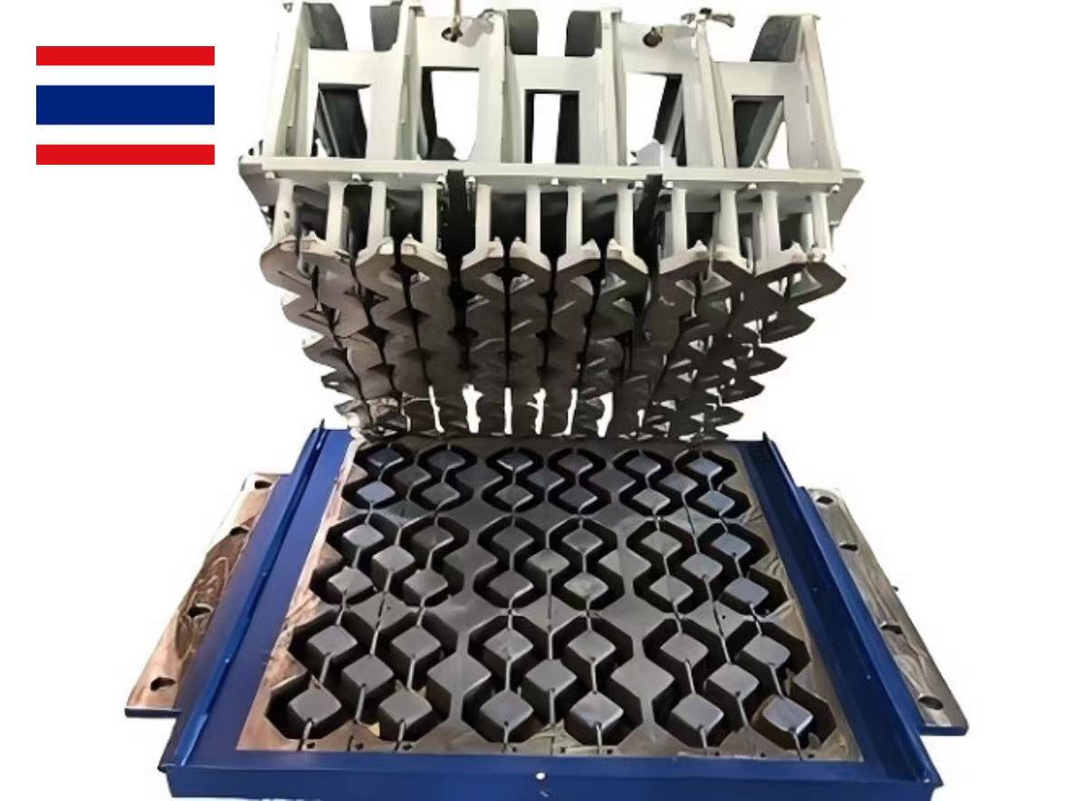
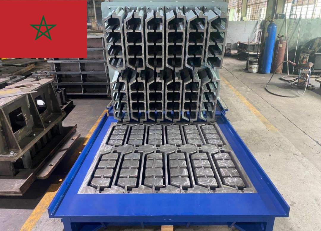
Mould access deserves a specific review because product changes connect tooling, handling, and machine setup. Confirm how the supplied mould assembly is installed and removed under the manufacturer's procedure. Ask which components move together, which are handled separately, and where the assembly is placed after removal. The buyer should obtain the actual component information needed to plan the approved handling arrangement.
Draw the route from the machine to the intended mould storage or service position. Identify turns, doors, changes in floor level, and locations occupied by other production activity. A route that looks clear while the line is empty may be obstructed by pallet stacks or finished products during a normal shift. Review it under the conditions in which the factory expects to perform a mould change.
Provide a defined destination for removed tooling. Leaving a mould beside the forming machine can turn a temporary operation into a lasting access obstruction. The destination should support the factory's inspection, identification, cleaning, and storage procedure. Any support or handling method must suit the actual assembly and be agreed through the appropriate equipment and site planning process.
Do not infer lifting requirements from a photograph or from a similar machine model. Confirm component mass, handling points, and the recommended procedure with the supplier, and involve qualified personnel when planning lifting equipment. The layout review should establish whether the proposed route and work area accommodate that procedure, rather than attempt to replace it.
Keep Mixer and Conveyor Service Points Reachable
Review mixer access from the perspective of the tasks performed on the supplied design. Ask the supplier to identify inspection openings, service covers, wear components, discharge equipment, and any areas requiring particular access. The requirement for one mixer design should not be assumed to apply to another. Record the relevant service-side orientation on the installation drawing.
Check the space around material conveyors and their drives. An accessible belt surface does not necessarily mean that a drive, bearing, tensioning arrangement, or removable guard can be serviced. The drawing should distinguish the route used to inspect the equipment from the space needed to remove or replace a component. Material spillage and temporary cleaning equipment should also be considered when reviewing that route.
Consider what is above and below the equipment. A mixer platform may require a planned access arrangement, while a conveyor crossing can restrict movement beneath it. Confirm the actual elevations, supports, and any supplier-provided platforms or stairs. The review should make the division between supplier equipment and site-provided access clear enough to include in the project scope.
Discuss how routine cleaning and inspections will be organized without allowing waste materials or tools to occupy the service route. A work area that is consistently blocked becomes less useful even when the drawing shows adequate space. Buyers should review both the geometric arrangement and the site's plan for keeping the access areas available.
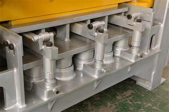
Component servicing can require a different access area from the one used during normal block forming.
Check Cabinet Doors and Hydraulic Service Areas
Show electrical cabinet doors in their intended service position on the drawing. Confirm how authorized personnel will approach the cabinet and whether adjacent equipment interferes with access. Applicable electrical and site requirements should determine the necessary clearances; a general-purpose walkway dimension is not a substitute for that review. Avoid placing a cabinet where its usable access depends on moving stored production.
Identify the hydraulic equipment included in the supplied configuration and the service points that need access. Relevant locations may include filters, inspection points, cooling equipment, and connections identified by the supplier. The layout should support the approved maintenance procedure and allow the factory to organize any required tools, containers, and replacement items without blocking other designated access.
Make space for removal as well as inspection. A component may be visible but difficult to take out if a wall, platform, or neighboring frame blocks its removal direction. Ask the supplier to identify significant replacement movements and any component handling needs. This is especially useful for equipment that is expected to remain in service for a long time while the surrounding factory becomes more densely occupied.
Coordinate Guards, Platforms, and Isolation Access
Guards and access structures form part of the equipment arrangement. Confirm their installed positions and, where relevant, their opening or removal movements. A drawing that omits a guard can give a misleading impression of the available space. Maintenance planning must retain the protective arrangement and follow the manufacturer's procedure for access and return to service.
Keep the locations required for authorized isolation and restart procedures identifiable. The equipment supplier and factory should agree which controls, disconnecting points, or other facilities are part of the supplied scope and which are provided on site. Their access must be reviewed against the relevant procedure and requirements. A layout decision should not depend on an operator reaching through production equipment to find a required point.
Review shared routes and adjacent operations during service work. A maintenance position may overlap a material delivery route or finished-product handling area. If that overlap cannot be eliminated, define how the factory will control the affected activity under its work procedure. Record that dependency in the layout review so it does not appear for the first time during a breakdown.
Verify Maintenance Routes on the Supplier Layout
Use a supplier drawing with the configuration and revision identified. Mark each important task, its access point, the required movement, and the destination of removed items. Add the building dimensions and site constraints needed to test the arrangement. A general drawing for a machine family should not be accepted as proof that a specific installation has adequate service access.
Walk through a representative service task with the supplier or installation team. Start from the normal operating arrangement and describe where personnel approach, where covers move, where handling equipment operates, and where removed components are placed. This review can be carried out on the drawing before installation, then confirmed against the installed arrangement through the agreed acceptance process.
A useful procurement-review observation is to ask who supplies each access structure and who confirms each clearance. If the quotation includes the machine but excludes a mixer platform, the platform still needs an owner and an agreed design process. Resolve these interfaces in writing so the contractor, supplier, and buyer are not each assuming that another party has covered the same requirement.
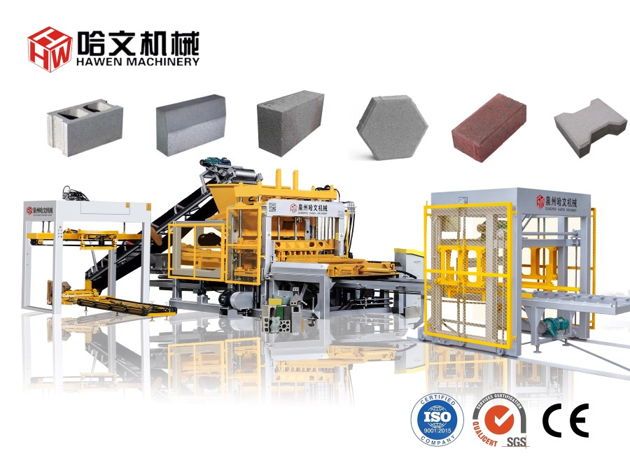
When comparing an automatic concrete block and paver production line, review the equipment configuration together with its maintenance arrangement. Ask for the actual installation and service information relevant to the selected equipment. The aim is to approve a workable layout for the complete supplied line, rather than choose a machine solely because its stationary outline fits an available floor area.
| Service task | Drawing evidence to request | Site question to resolve |
|---|
| Mould removal | Removal direction, handling information, route, and destination. | Can the route remain available during the planned changeover? |
| Mixer servicing | Service-side orientation, openings, elevations, and access structures. | Which platforms or other access items are included in the supply? |
| Conveyor component work | Drive and tensioning locations, guards, and removal movements. | Do columns, crossing conveyors, or stored materials obstruct the task? |
| Cabinet and hydraulic service | Door positions, service points, and component removal directions. | Have the applicable service procedures and clearance requirements been reviewed? |
| Guard and isolation access | Installed protective arrangement and identified authorized access points. | Is responsibility clear for supplier-provided and site-provided facilities? |
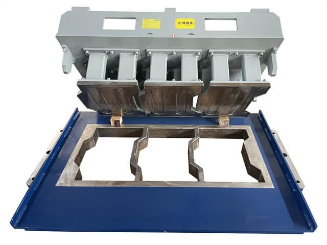
A mould-change review should identify the removal route and a suitable destination for the tooling.
FAQ
Is there one clearance dimension suitable for every block production line?
No. Confirm the supplied equipment's service requirements, the building constraints, and applicable site requirements. Avoid using a generic dimension without reviewing the actual task.
Can a walkway also serve as temporary maintenance space?
That depends on the task and site requirements. Identify any shared use explicitly and define how the area will be made available and controlled under the factory's procedure.
Why is a machine footprint drawing insufficient?
It may show the installed equipment outline without the movement of doors, guards, removable components, or handling equipment. Request the service information relevant to the selected configuration.
Should removed moulds remain beside the machine?
Use a defined storage or service destination suitable for the tooling and the factory's procedure. Temporary placement should not turn into an obstruction to operating or maintenance access.
When should maintenance access be confirmed?
Review it before approving the layout and supply interfaces, then confirm the installed arrangement through the agreed installation and acceptance process.
Conclusion
Maintenance access includes more than the space around the stationary equipment. Review mould removal, mixer and conveyor service points, cabinet doors, hydraulic components, guards, and the routes required by authorized work procedures. Keep permanent access clear and document any temporary sharing arrangement.
Before approving a block production line layout, ask the supplier and site team to demonstrate representative service tasks on the actual project drawing. Confirm the required movements, component destinations, building constraints, and responsibilities. That review gives buyers a practical basis for accepting a layout that remains usable when the line needs inspection, cleaning, or replacement work.





 Tel: +86-13905968794
 Email: export@hwmachines.com
 MP/WhatsApp: +86-13905968794
 Manufacturer Address:Nanan,Quanzhou City,Fujian Province,China