How to Manufacture Concrete Paver Layers for Mechanical Installation is a practical topic for buyers and plant managers who want a more stable block making machine workflow. The goal is not only to explain the issue, but to give a clear method that supports better output, cleaner operation, and stronger customer confidence.
In a professional concrete products factory, the block machine, material system, mold, pallet circulation, control system, and operator routine must work as one process. A good solution therefore looks at the whole line before changing one visible setting.
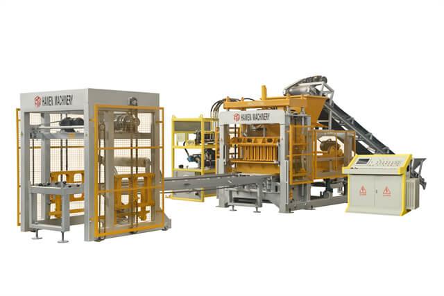
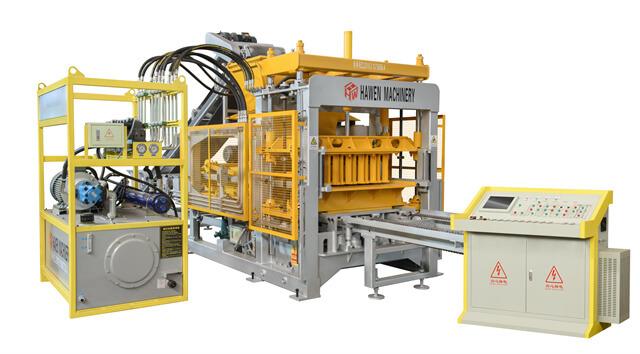
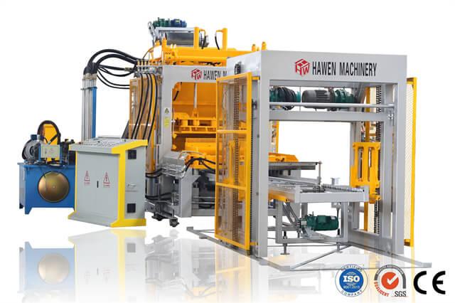
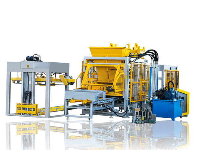
The press and mold must produce the geometry needed for stable, machine-handled layers.
1. Define the mechanical-installation requirement
Mechanically installed interlocking concrete pavement uses equipment to pick up and place a prearranged layer of pavers. The method shifts part of the coordination upstream: the producer must deliver layers that match the installer’s clamp, pattern, orientation, and project layout. A paver that meets its individual dimensions may still be unsuitable for machine placement if the layer shifts, cannot be gripped evenly, or arrives in an orientation that slows the paving crew.
Start with the project and installation contractor, not only the press. Collect the paver profile, approved laying pattern, layer footprint, clamp type, placement direction, joint requirements, and details for edges, inlets, and transitions. Ask whether the site uses one pattern throughout or needs special layers for starts and offsets. The design professional approves pavement and product requirements; the manufacturer translates the released drawings into a repeatable production and packaging plan.
2. Translate the laying pattern into mold and pallet geometry
Lay out the pattern in a scaled drawing using the actual pallet or production board dimensions. Check cavity spacing, mold walls, edge clearances, orientation, and the number of units per layer. The goal is not simply to maximize cavity count. A dense arrangement that leaves fragile edges or prevents the finished layer from nesting securely may reduce usable output and create more breakage during handling.
Consider how each layer relates to the adjacent layer and to the installation machine. Running bond, cross-joint arrangements, herringbone, and purpose-designed patterns have different edge conditions and interlock. Some patterns require a starting offset or a manual border before a machine can continue. Make these transitions explicit in the drawing, layer label, and packing instructions so the factory does not ship a geometrically correct layer in the wrong orientation.
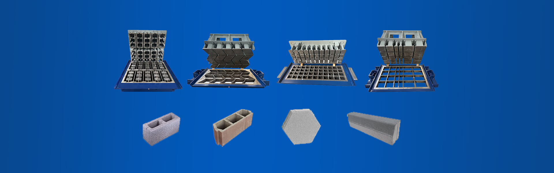
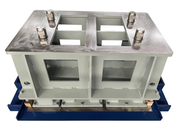
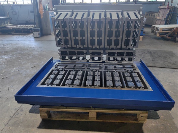
Evaluate the forming pallet, mold, tamper head, and product release as one tooling set. Confirm machine interface dimensions, wear surfaces, maintenance access, and how a cavity can be inspected. Hawen Machinery designs molds compatible with leading machine brands, including Masa, Hess, Zenith, Poyatos, Besser, Tiger, Columbia, Quadra, and Omag, using released specifications for fit. The molds receive heat treatment for wear resistance, with hardness tested at HRC59-61.
Layer configuration begins with the paver drawing and the installation equipment interface.
3. Control the individual paver before controlling the layer
A stable layer begins with stable units. Verify length, width, height, squareness, chamfer, spacer-bar profile, and face condition against the approved drawing and product specification. Check units from several cavities rather than sampling only one convenient position. If a pattern contains different orientations or special shapes, identify the critical surfaces for clamping and neighboring-unit contact. Use a sampling plan suited to the project and do not invent acceptance limits beyond the governing specification.
Track changes over a production run. Mold wear, fastener movement, pallet condition, mix moisture, feed distribution, and compaction can shift dimensions or edge quality. When measurements drift, locate whether the change is cavity-specific, time-dependent, or common to the whole mold. Record the mold identification and machine settings with the sample. This gives the quality team a useful diagnostic path instead of encouraging operators to compensate with an unrelated adjustment.
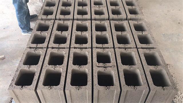
Mechanical clamps need reliable exterior contact. Bulged sides or inconsistent edge profiles can weaken grip and make a layer hard to place squarely. Moisture and feed conditions can contribute to bulging, while mold condition and demolding movement can create other defects. Inspect the product immediately after release and again after initial handling. If units are unstable at that stage, do not rely on packaging to force them into a layer; correct the forming cause first.
4. Build layers that stay square through gripping and transport
The layer must retain its designed footprint while it is lifted, moved, stacked, wrapped, and placed. Confirm that the clamp fingers can contact the intended surfaces without crushing spacers or striking chamfers. If the layer depends on a particular orientation, mark it clearly on the pallet or package. Test the complete pickup, turn, set-down, and restack sequence; a layer that is stable on a static board may shift under acceleration or uneven support.
Spacer bars or nibs help preserve joint spacing during placement, but their height, projection, and continuity should come from the product design and governing specification. The installation contractor may need consistent joint widths, a specific pattern, and pavers that can be gripped without edge damage. Coordinate those needs with the engineer and installer. Do not alter the paver profile to imitate another product unless the revised geometry is approved and checked for pavement performance.
Pallet flow and layer handling should be coordinated from forming through shipment.
5. Coordinate curing, finishing, and release criteria
Pavers need enough stability for the intended handling sequence. Define when inspection occurs, when layers may be stacked, and which surfaces must remain protected. Avoid using a single elapsed-time rule without reference to the mix, curing conditions, product dimensions, and handling method. Observe representative layers through demolding, transfer, curing, packaging, and trial pickup. Record the first point at which movement, corner damage, or loss of squareness appears.
Face texture and color may matter to the project, but visual acceptance should be separated from dimensional and handling checks. Use reference samples under consistent lighting and compare like products. If the layer contains blended colors or multiple finishes, specify the order and quantity of each appearance. Maintain lot identity through curing and packing so the installer can trace a field concern to a production period, mold, mix, and operator shift.
6. Diagnose layer and machine-placement problems systematically
If a clamp cannot grip, inspect the paver side profile, layer spacing, clamp alignment, and pickup orientation before changing the mold. If the layer slips or spreads, check edge geometry, unit dimensions, support condition, and whether the pattern interlocks as intended. Recreate the failure with the same clamp and pallet arrangement used on site. Small controlled trials make it easier to distinguish a tooling issue from a packaging or operating issue.
If layers arrive out of square, inspect pallet flatness, stack alignment, straps or wrap, forklift entry, and transport support. Compare the first packaged layer with the layer after shipment. If the defect appears before shipment, review forming, transfer, curing, and stacking. If it appears only after delivery, examine loading and restraint. Keep photographs at each stage; otherwise the factory may adjust the mold to compensate for damage introduced by the logistics chain.
7. Match machine capacity to tooling and downstream handling
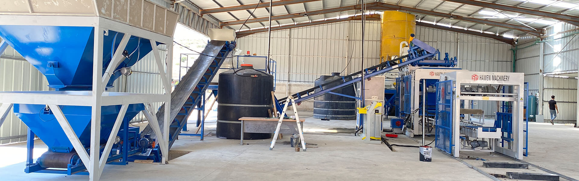
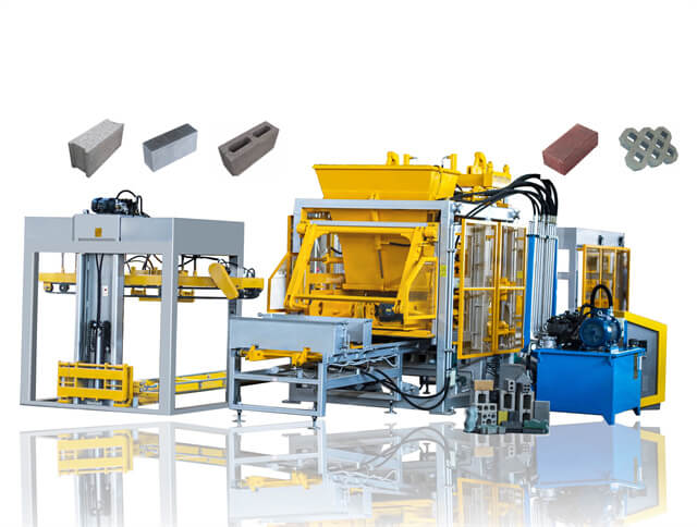
Select a block making machine around the required product geometry, mold footprint, daily order profile, changeover plan, curing capacity, and pallet circulation. A high nominal press rate is not the same as a stable shipment of machine-ready layers. Confirm the mixer and batching system can feed the product consistently, the curing route supports the planned cycle, and packaging can maintain layer alignment. Discuss expected future patterns before finalizing the line layout.
Hawen's four-shaft vibration-box arrangement places eccentric blocks outside the housing to reduce internal resistance and support even compaction. A SIEMENS S7-200 PLC with touch-panel operation and remote monitoring helps operators review machine status and production parameters. These capabilities support repeatable process control, but do not replace approved product drawings, site trials, or acceptance tests. Review the intended paver pattern, clamp interface, local electrical supply, and service plan when evaluating a brick making machine or block line.
8. Release production with a traceable coordination package
Before routine output, issue one controlled package containing the approved paver drawing, pattern and layer map, mold identification, pallet specification, product inspection plan, sample approval, packaging method, and installer handling instructions. Identify revision status and responsible approvers. If the project changes the clamp, paver layout, joint requirement, or edge detail, review the impact before modifying production. Inform the sales, tooling, quality, and line teams from the same released document.
Use an initial production run to confirm that the drawing translates into stable physical layers. Measure selected units, test handling with the actual or representative clamp, inspect after stacking, and evaluate the package after a realistic transport simulation if required. Record corrective actions and close them before shipping the production lot. This does not need to become an elaborate certification exercise; it does need to provide evidence that the agreed product arrives in the agreed configuration.
Action checklist
Obtain the installer's clamp, pattern, layer orientation, joint, and transition requirements before releasing the mold drawing.
Lay out the mold against the actual pallet footprint and inspect cavity access, edge clearances, and layer interlock.
Measure representative units from multiple cavities, including clamp-contact sides and spacer features.
Run the layer through pickup, transfer, stacking, packaging, and placement trials using realistic supports.
Coordinate curing, pallet condition, labeling, transport restraint, and site orientation in one controlled package.
Keep production quality separate from installation acceptance, and resolve field feedback through traceable records.
A mechanically installed paver project is a chain of compatible decisions, from the mold cavity to the contractor's first placement line. When the block machine producer, designer, and installer agree on the same layer drawing and verify it in a controlled trial, production becomes predictable and the job site receives more than pavers: it receives a system ready to work.
FAQ
What makes a concrete paver suitable for mechanical installation? Its geometry, side profile, layer pattern, and packaging must match the installer’s clamp and placement sequence, in addition to meeting the project product specification.
Should pavers be arranged into the final layer at the factory? For many mechanized systems, producing the intended layer pattern at the factory avoids manual rearrangement, but confirm the project and installation equipment requirements first.
Why does mold layout matter for machine-laid pavers? Mold and pallet geometry determine cavity arrangement and can affect layer footprint, edge stability, and how efficiently the product moves through the line.
Can a standard paver pattern always be installed mechanically? No. Some patterns need starting offsets, manual borders, special layers, or site-specific transitions. Confirm them with the installer before production.
What should be checked if layers shift during clamping? Review unit side geometry, layer squareness, spacer features, clamp contact, pallet support, and pickup orientation using the actual handling sequence.
Do spacer bars need to match the clamp? Spacer geometry should satisfy the approved product and joint design while allowing secure handling. Coordinate the drawing with the pavement designer and installer.
Does a successful factory handling trial guarantee installation quality? No. It verifies a manufacturing and handling interface. Site layout, bedding, alignment, installation practice, and contract acceptance remain separate controls.





 Tel: +86-13905968794
 Email: export@hwmachines.com
 MP/WhatsApp: +86-13905968794
 Manufacturer Address:Nanan,Quanzhou City,Fujian Province,China