How to Specify Segmental Retaining Wall Blocks for Production is a practical topic for buyers and plant managers who want a more stable block making machine workflow. The goal is not only to explain the issue, but to give a clear method that supports better output, cleaner operation, and stronger customer confidence.
In a professional concrete products factory, the block machine, material system, mold, pallet circulation, control system, and operator routine must work as one process. A good solution therefore looks at the whole line before changing one visible setting.
A retaining wall unit belongs to a designed system, so its connection profile must remain controlled.
1. Define the retaining wall system before the block
A segmental retaining structure is a system, not simply a stack of ordinary hollow blocks. Its performance depends on the facing elements, element-to-element connection, backfill, drainage, foundation, structure geometry, and, where designed, geosynthetic reinforcement. Begin with the site-specific design and intended use. Do not choose a element by appearance or copy a profile from another supplier without engineering review.
Clarify whether the design is a gravity structure or a reinforced-soil structure. The design professional considers height, surcharge, soil conditions, groundwater, slopes, nearby structures, and global stability. A manufacturer can provide element data and system properties, but a factory or mold supplier should not select reinforcement length or structure dimensions without the responsible engineer's design.
Identify who owns the design, who approves the product, and what submittals are required. CMHA's segmental retaining structure guidance treats design, construction, and inspection as connected responsibilities. For commercial or critical projects, geotechnical and structural review may be needed. Make those roles clear before a block machine producer commits to a manufacturing drawing.
2. Freeze unit geometry and connection details
Prepare a controlled drawing with length, height, depth, face batter, split or smooth texture, top and bottom surfaces, core layout, and critical tolerances. Show the interlock feature, such as a lip, key, pin, clip, or other approved connection. The shape must work with the specified neighboring elements, caps, corners, and reinforcement connection, not only with one display sample.
Confirm whether the product family includes standard elements, corner elements, caps, setback options, and elements with connection features. Define how each variant is identified and oriented. A visually similar block can have a different shear interface or setback and may not be interchangeable within a tested or engineered system. Keep drawings and product codes under revision control.
Do not assume a geogrid that fits physically is compatible structurally. Connection strength, shear behavior, pullout, and long-term reinforcement properties may require product-specific evidence. The engineer and system supplier should verify compatibility for the proposed soil and layout. Any change to the face element, connection geometry, or reinforcement should trigger review before manufacturing release.
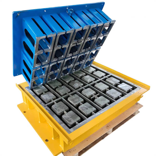
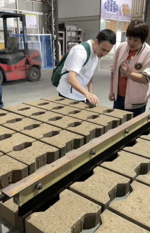
Core and face geometry should match the approved retaining wall unit and its test evidence.
3. Specify material properties and acceptance evidence
Identify the applicable product specification and test methods in the contract. CMHA sample specifications for segmental retaining wall elements reference ASTM C1372 for dry-cast SRW elements and ASTM C140 for sampling and testing. They also identify ASTM C1262 for freeze-thaw evaluation where exposure requires it. Confirm the current edition, jurisdictional requirements, and project amendments before writing the purchase specification.
State the required dimensions, permissible variation, compressive performance, absorption, density class if relevant, appearance, and durability evidence. Do not copy acceptance values from another climate or project without checking the contract and engineer's direction. Freeze-thaw requirements depend on exposure and the specification; avoid implying that one test result universally qualifies a element in every environment.
Clarify sampling frequency, test laboratory, lot definition, report format, and what happens when a result fails. Product certification and test evidence should identify the actual element family and manufacturer. If several manufacturing lines or material sources are involved, establish how manufacturing lots are traced to the evidence and whether additional qualification is necessary.
4. Translate the approved drawing into production tooling
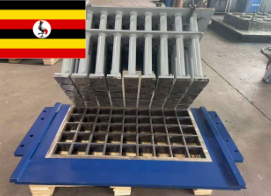
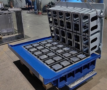
The mold drawing must preserve face dimensions, connection features, core geometry, top and bottom fit, and any texture required by the system. Check the interface against the target block machine, tamper head, pallet, and manufacturing direction. Review tolerances together with wear allowance so the element remains within specification throughout a planned maintenance interval.
Hawen Machinery designs molds compatible with leading platforms including Masa, Hess, Zenith, Poyatos, Besser, Tiger, Columbia, Quadra, and Omag. Tooling follows the approved interface and product drawing for accurate fit and repeatable operation. Heat treatment improves wear resistance, and mold hardness is verified at HRC59-61. Confirm the machine model, connection details, element drawing, steel, and acceptance checks for each order.
A block mold trial should include a representative batch, intended pallet, manufacturing recipe, demolding, and stacking. Inspect interlock features and face geometry at multiple cavities, not just one selected element. Check fit with caps and connecting elements using a simple assembly jig or approved sample structure. Record the tooling revision and acceptance sign-off before releasing serial manufacturing.
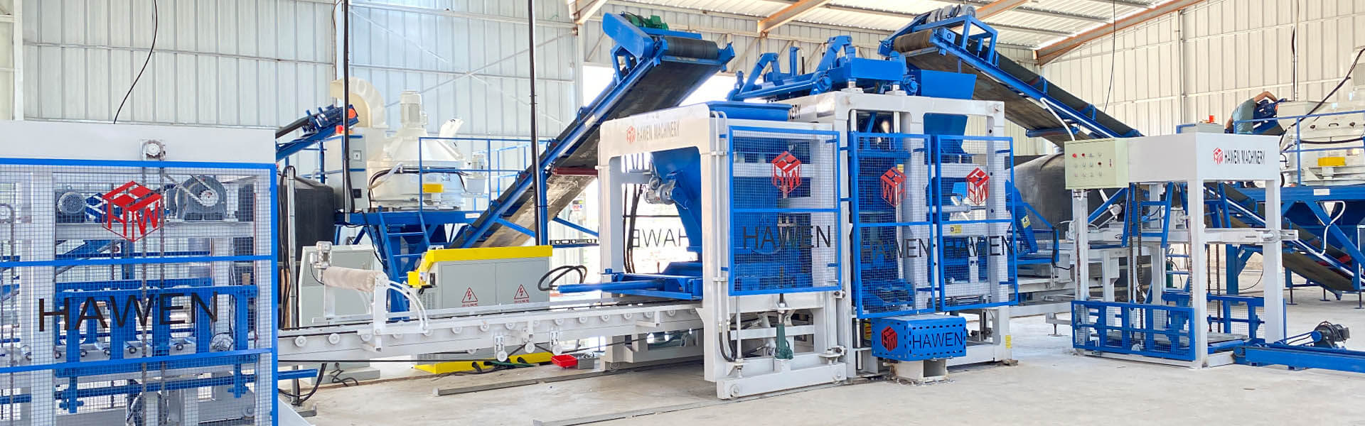
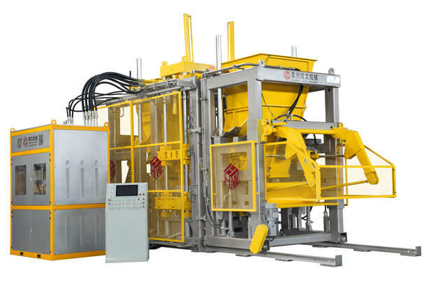
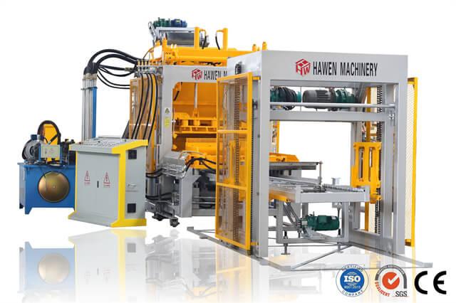
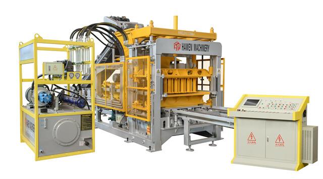
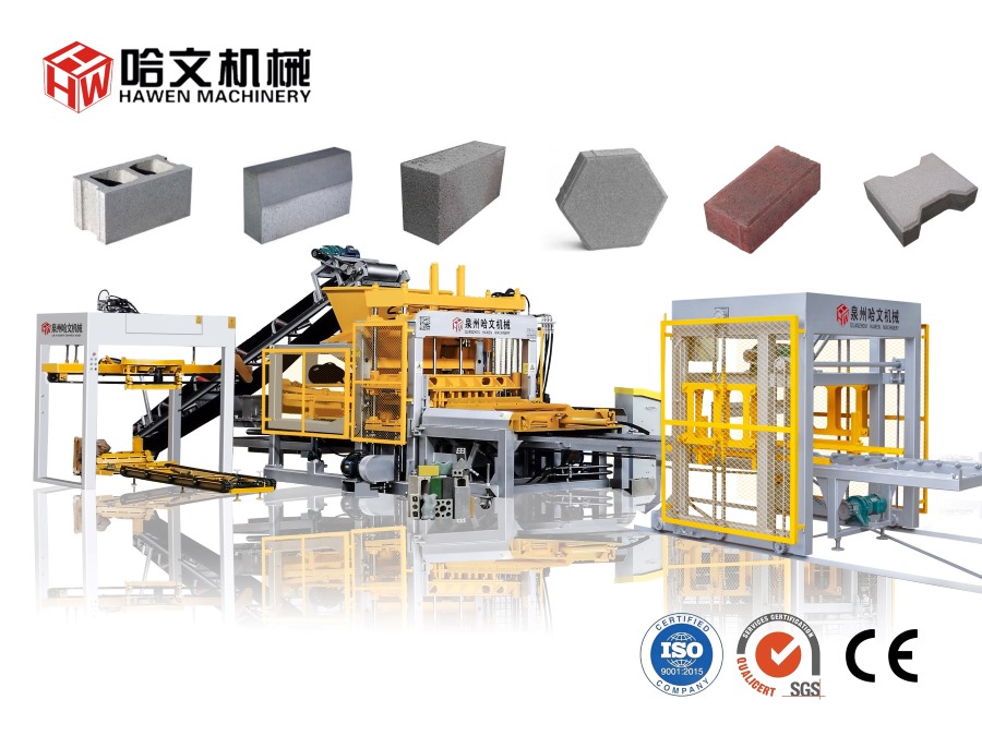
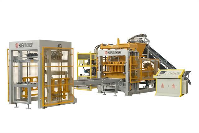
Equipment selection follows the required unit family, tooling interface, output plan, and quality checks.
5. Control the production variables that affect fit
Keep incoming aggregates, cementitious materials, pigments, and water within the approved process controls. A change in grading or moisture can alter feeding and compaction, which may show up as inconsistent face texture, edges, or connection dimensions. Use a controlled recipe and record material lots so a field complaint can be traced to the manufacturing period and tooling cavity.
Hawen Machinery's four-shaft vibration box places eccentric blocks outside the housing to reduce internal resistance and promote uniform compaction. The correct settings still depend on mix behavior, mold design, board support, and cycle sequence. Confirm the product at startup and after relevant changes; do not treat an equipment feature as a substitute for dimensional checks or acceptance testing.
Use the SIEMENS S7-200 PLC and touch-panel control system to maintain an approved sequence and monitor operating status. Remote monitoring can assist Hawen engineers with troubleshooting and parameter review. Restrict recipe edits, record alarms and changes, and retain the approved settings for each element family. A process record supports repeatability; product acceptance remains tied to the specified tests and inspection plan.
6. Coordinate production specifications with field construction
The element specification should work with the installation details. Draw the leveling pad, first-course embedment, drainage aggregate, outlet route, filter separation, backfill, and coping. Water management is a design requirement, not an accessory to add after the face elements are selected. The responsible engineer should address surface runoff and subsurface water for the site conditions.
For reinforced walls, show geogrid type, strength direction, elevation, length, connection, overlap rules, and placement sequence on the engineered drawings. The installer must place the reinforcement as designed and maintain the required interaction with the elements and backfill. Do not infer grid spacing from block height alone or substitute a different connection without approval.
Construction inspection should verify foundation preparation, level and alignment of the first course, drainage continuity, backfill material, compaction sequence, reinforcement orientation, and element connection. The element supplier may help identify products and handling instructions, while the site engineer or inspector confirms the installed system. Keep photographs and inspection records before each reinforced lift is covered.
7. Diagnose production and field fit problems
If elements do not interlock smoothly, compare measured profiles with the released drawing. Check mold wear, fasteners, tamper alignment, pallet flatness, feed distribution, and demolding movement. Inspect multiple cavities and manufacturing times. Segregate nonconforming material while the quality team establishes whether the issue is tooling, process variation, drawing interpretation, or an incompatible mating component.
If a completed structure shows movement, bulging, settlement, or drainage problems, do not diagnose it as a block defect from a photograph. Document location, loading, water conditions, construction sequence, reinforcement records, foundation observations, and movement over time. Refer the issue to the engineer of record and qualified retaining-structure professional; stabilize the site if directed by the responsible safety authority.
If a test result falls outside the requirement, verify specimen identification, test method, sample conditioning, and lot traceability before changing the mix. Review recent material, machine, mold, curing, and operator changes. Repeat tests only when permitted by the specification. Record corrective action and obtain written disposition from the project authority before releasing affected elements.
8. Select equipment and release the product family
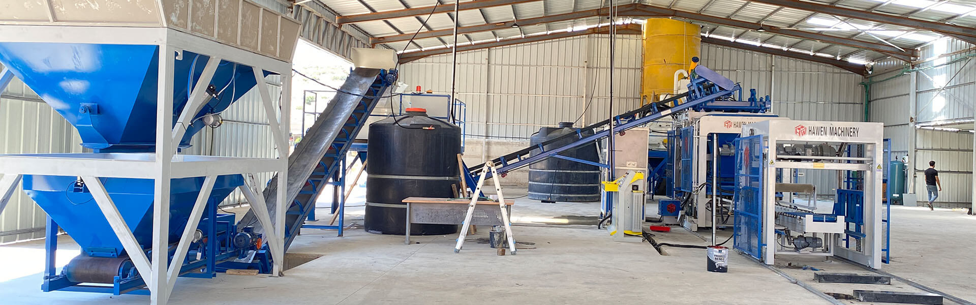
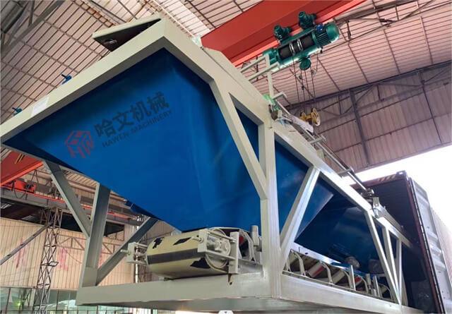
Match machine capacity to the required element sizes, mold changeovers, output plan, batching, mixing, curing, pallet circulation, and finished-product handling. A large press cannot compensate for inadequate mold interfaces or a downstream bottleneck. Share the approved SRW drawing, target volumes, material plan, destination standards, power supply, and future product mix with Hawen Machinery when requesting a proposal.
Release manufacturing only after drawings, material specifications, tooling, sample elements, test requirements, packaging, and installation instructions are aligned. Hawen can support equipment and mold discussions, while the project engineer approves the retaining-structure design and system properties. That separation lets the plant deliver consistent elements without presenting an equipment quote as engineering approval for the finished structure.
Action checklist
Obtain the engineer's system design and identify gravity or geosynthetically reinforced construction.
Freeze the unit profile, connection features, corners, caps, tolerances, and approved component compatibility.
State applicable product standards, test methods, exposure requirements, lot traceability, and acceptance process.
Verify mold interface, machine model, pallet, wear allowance, and sample-wall fit before production release.
Coordinate drainage, foundation, reinforcement, backfill, and field inspection details with the design team.
Document startup trials, testing, corrective actions, and written approval for substitutions or changes.
Reliable segmental retaining walls begin with a product that belongs to a complete, site-specific system. Freeze the connection geometry, substantiate the unit properties, control the mold and production lot, and coordinate drainage and reinforcement with the engineered details. That discipline gives block producers a clear manufacturing target and gives project teams confidence that the delivered units match the design they intend to build.
FAQ
Are segmental retaining wall blocks the same as ordinary hollow blocks? No. SRW units are designed with specific geometry and connections for a retaining-wall system; ordinary masonry units should not be substituted without engineering approval.
Who determines the block size and reinforcement for a retaining wall? The responsible design professional uses site soils, water, geometry, loading, and system properties to establish the design.
Which standards should be listed for SRW units? Use the standards and editions required by the project; CMHA sample specifications reference ASTM C1372, C140, and, where exposure requires, C1262.
Can a geogrid from another supplier be used with the same block? Only after the engineer verifies unit connection, test evidence, soil conditions, and compatibility for the proposed system.
What should be checked during a mold trial? Inspect dimensions, interlock fit, face profile, multiple mold cavities, demolding, pallet support, and fit with caps or mating units.
Does a mold compatible with a machine brand guarantee SRW performance? No. Machine fit supports production, while system design, unit qualification, testing, and field installation determine retaining-wall suitability.
What records help investigate a retaining wall unit complaint? Keep the approved drawing, mold ID, material batch, production settings, test reports, delivery lot, and site installation records.





 Tel: +86-13905968794
 Email: export@hwmachines.com
 MP/WhatsApp: +86-13905968794
 Manufacturer Address:Nanan,Quanzhou City,Fujian Province,China