How Hopper Material Level and Feeding Rhythm Affect Mould Filling Uniformity
When blocks from one production pallet have different weights, heights or corner quality, operators often adjust vibration or hydraulic pressure first. However, the difference may have started before compaction. If the mould cavities do not receive a similar quantity and distribution of concrete, vibration can only compact the material that is already present. It cannot reliably move a large shortage from one cavity to another.
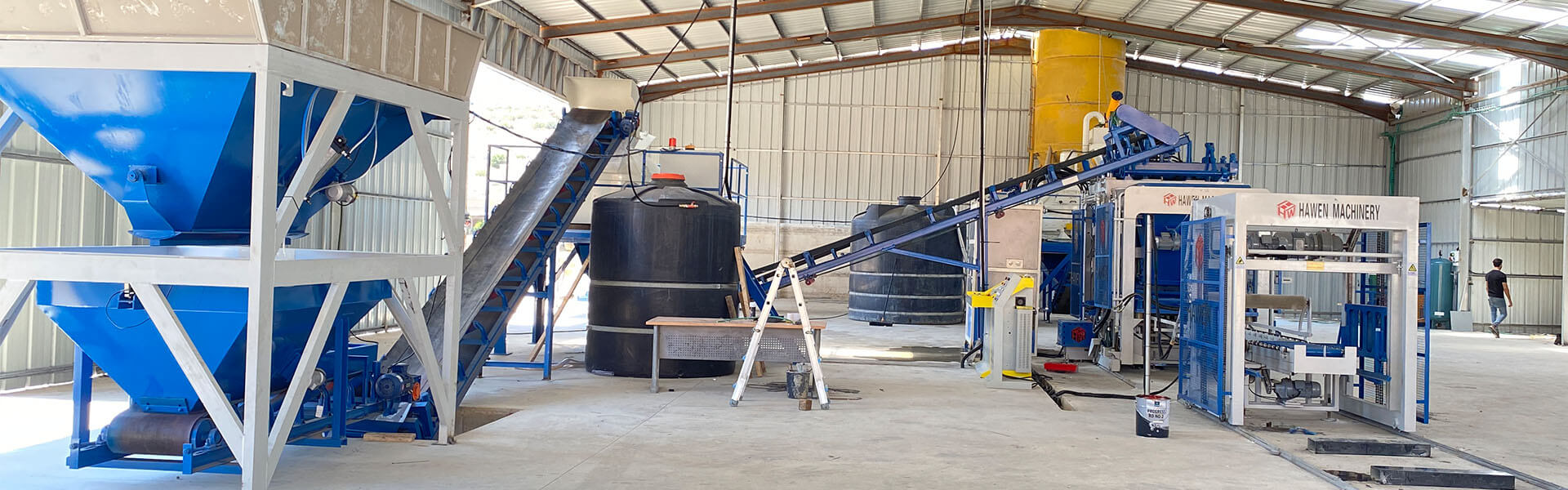
The feeding system links mixed concrete to the mould. Its performance depends on hopper level, discharge opening, material consistency, cart travel, agitation, scraping and timing. This article explains how those factors work together and provides a practical method for diagnosing uneven filling.
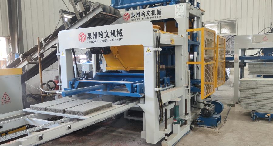
Good Compaction Starts with Uniform Filling
Dry or low-slump concrete does not flow like ready-mix concrete. It contains limited free water and depends on mechanical distribution and vibration to rearrange particles. The feeding cart must carry material over the mould, release it, spread it across the cavity field and withdraw without pulling an excessive amount back out. This process must repeat every cycle.
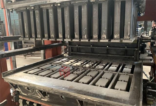
A mould can contain many cavities spread over a large pallet. The cavities closest to the hopper may fill differently from those at the far end. Hollow-block cores, thin webs and corners introduce additional resistance. If one area starts with less material, the finished units in that area may have lower mass, open texture, incomplete webs or reduced height. If another area is overfilled, it may compact differently or leave excessive material around the mould.
Uniform filling does not mean that every loose cavity contains exactly the same visible height before vibration. Different geometry may require controlled settling. It means the feeding process supplies the intended material mass and distribution so that all products reach consistent dimensions and density after the programmed forming cycle.
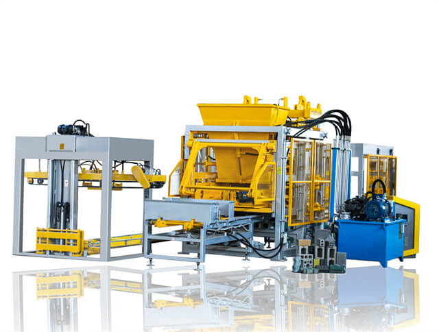
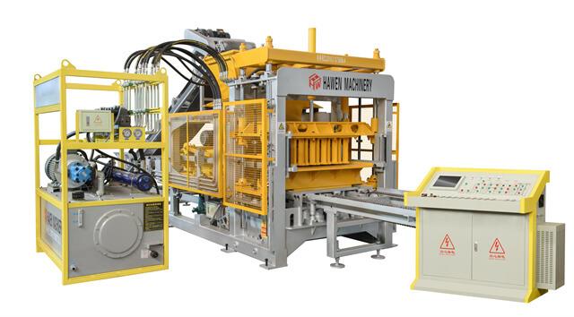
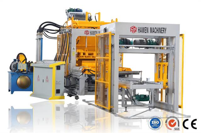
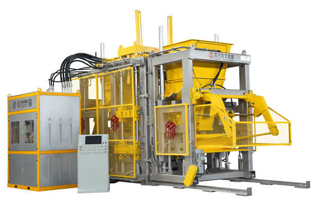
The feeding system should therefore be evaluated as part of the forming system. A high-performance block making machine needs stable material supply just as much as accurate vibration and hydraulic control. Faster movement is useful only when it remains repeatable and does not create a front-to-back imbalance.
Why Hopper Material Level Matters
The amount of concrete above the hopper outlet affects the pressure and flow of material into the feeding cart. When the hopper is nearly full, the outlet may deliver material differently than when only a shallow layer remains. If the level changes widely during normal operation, the cart can receive a different mass on otherwise identical cycles.
A very low level can expose the outlet intermittently and allow the cart to leave before it is fully charged. Operators may see the shortage only after several defective pallets appear. A very high level can increase loading on the gate, compact material near the outlet or encourage bridging if the mix is sticky. The suitable operating band depends on hopper geometry, outlet size and concrete behavior.
Level sensors can help maintain a controlled band. Their location and technology should suit dusty concrete service. A sensor should detect the useful material level rather than buildup on the hopper wall. Test the high and low signals under actual production conditions, and verify that the upstream conveyor responds in time. A delayed conveyor can let the hopper fall below the minimum before new material arrives.
Visual inspection remains valuable. Check for material hanging on one wall, a stable arch above the outlet, or a channel in which only the center flows. These patterns mean that the indicated level may not represent the usable material available to the cart. Hopper wall angle, surface condition, outlet design, vibration devices and concrete moisture all influence this behavior.
Do not add uncontrolled hopper vibration simply because material occasionally sticks. Excessive vibration can compact dry concrete in the hopper, separate particles or transmit unwanted vibration to the machine. Use the machine supplier's approved agitator or vibrator arrangement and operate it for the intended duration.
Feeding Rhythm and Cycle Coordination
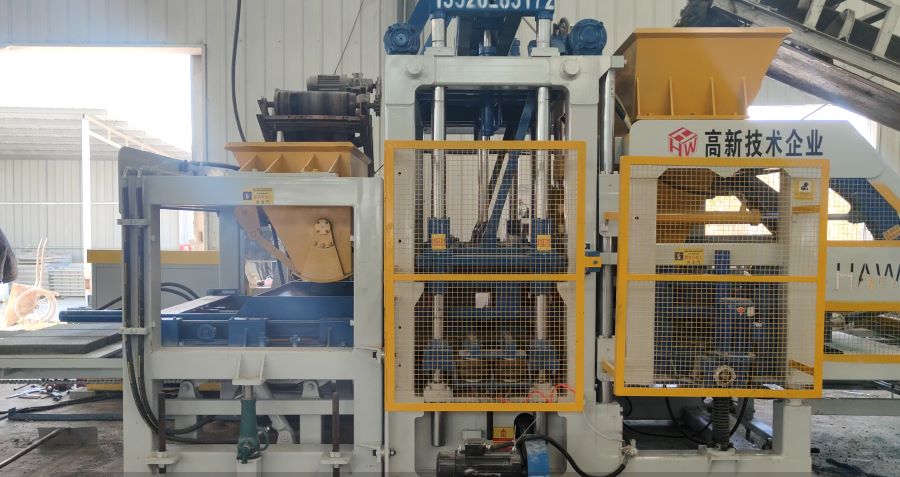
Feeding rhythm includes the time when the hopper gate opens, how long the cart is charged, the cart's forward speed, its movement over the mould, agitation or preliminary vibration, scraping and return. Each step affects how material reaches the cavities. A small timing change can alter the amount carried or the point at which it is released.
The cart should begin each cycle from a repeatable material condition. If concrete continues falling into the cart while it starts moving, early and late cycles may receive different distributions. If the gate closes slowly, the rear part of the cart may be overfilled. Check mechanical gate movement and cylinder timing before compensating through longer feeding time.
Forward speed must allow material to settle into the cavity field. Moving too quickly may carry material over narrow sections without sufficient entry. Moving too slowly can extend cycle time and may cause excessive pre-compaction in the first cavities. Some products benefit from one or more controlled passes, agitation or short filling vibration. These settings should be stored as a product-specific recipe.
Return movement matters too. A scraper or grid positioned too low may drag material from full cavities; positioned too high, it can leave uneven piles that interfere with the tamper head or spill around the mould. Inspect its straightness and clearance across the complete width. Wear at one side can create a repeated left-to-right pattern.
The PLC must coordinate feeding with the mixer discharge and material conveyor. If one mixer batch reaches the hopper just as the level becomes critical, several cycles may use concrete from different mixing times or moisture conditions. A stable buffer level allows the forming machine to operate continuously without making the hopper so large that material waits too long.
How Concrete Mix Behavior Changes Filling
The same feeder setting will not handle every concrete mix equally. A mix that is too dry may bridge, resist movement into narrow cavities and separate during repeated agitation. A mix that is too wet may stick to the cart, grid, scraper or mould. It can leave patches that build up cycle after cycle and gradually change the filling pattern.
Aggregate grading controls flow through restricted spaces. Oversized particles can block thin hollow-block webs, while excessive fines may increase cohesion and sticking. Changes in crushed aggregate shape also influence internal friction. Maintain agreed grading limits and remove oversize contamination before trying to solve every filling defect through machine timing.
Aggregate moisture changes both workability and effective water. Rainfall or a new stockpile layer can cause the material to behave differently even though the programmed mixer water is unchanged. Compare moisture records and fresh mix condition whenever filling deteriorates suddenly. Adjust the recipe through a controlled water-correction procedure.
Mixing uniformity is equally important. Dry pockets, balls of cement or local wet clumps do not distribute consistently. The concrete mixer must provide a homogeneous batch before it enters the hopper. Inspect blades, liners, discharge gate and mixing time when variation appears within one batch.
Material waiting time should remain reasonably stable. Concrete left in the hopper during a prolonged stop can stiffen or form a surface crust. When production restarts, the first cycles may behave differently. Define a restart procedure that includes inspection and removal of unsuitable material instead of mixing old and fresh material without evaluation.
Mould and Product Geometry
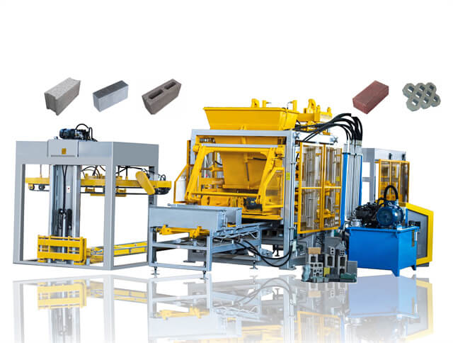
A solid rectangular brick is generally less sensitive to narrow flow passages than a hollow block with thin webs. Grass pavers, drainage blocks and complex interlocking shapes can contain isolated pockets that need deliberate feeding action. Large curbstones require a greater material volume and can expose limitations in cart capacity.
Mould layout influences the direction of material travel. Cavities at the leading edge may receive the first material, while those at the far edge depend on continued flow. Review the layout together with cart direction, agitator design and grid pattern. A feeder optimized for one mould may need a different recipe or insert for another.
Core and cavity surfaces must remain clean. Hardened material changes the opening and blocks flow into corners. Wear can also increase some cavity volumes or alter edges. If a weight or height difference always follows the same mould position, inspect the concrete block mould, tamper shoes and feeder path before changing the complete recipe.
For face-mix pavers, base and surface layers have separate feeding requirements. The face mix uses finer material and a smaller quantity, so small distribution errors are visible as thickness or color differences. Base filling must still remain uniform because an uneven base layer changes the support and final face position.
How to Measure Filling Uniformity
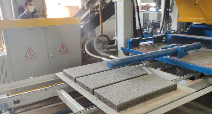
Start by mapping every cavity. Give each position a fixed number based on operator side, hopper side and feeding direction. Mark sample products immediately after demoulding so their cavity positions are preserved. Without a map, apparently random defects cannot be linked to a specific part of the mould or feeder.
Weigh products from selected positions using the same timing and method. Fresh unit mass provides a fast indication of material distribution, although it must be interpreted with moisture and geometry. Measure height at defined points and inspect webs, corners and surface texture. Use several consecutive cycles rather than relying on one pallet.
Calculate or review the spread between the heaviest and lightest units and look for a pattern. A consistent difference from near side to far side suggests distribution or scraping. A single repeating light cavity suggests a local blockage or mould issue. Variation that moves randomly may point toward changing hopper supply or material consistency.
For products with different shapes in a combination mould, compare each position with its own target mass rather than treating all pieces as identical. Final strength and dimensional testing should follow the applicable product standards. Fresh mass is a process indicator, not a replacement for compliance testing.
| Measurement | What it can reveal | Important control |
|---|
| Fresh unit mass by cavity | Material distribution differences | Same scale and weighing time |
| Height by cavity | Underfill, overfill or compaction pattern | Defined measuring points |
| Hopper level during cycles | Relationship between supply and defects | Record actual high and low points |
| Cycle-step time | Gate, cart or sensor delay | Compare under normal load |
A Practical Adjustment Procedure
First, confirm material stability. Check current moisture, grading, mixer discharge and whether old material remains in the hopper. Clean the mould and feeder, inspect the scraper, and confirm that the cart and gate move freely. Mechanical resistance should be corrected before timing is optimized.
Second, establish a controlled hopper-level range. Run enough cycles to compare filling near the high and low ends of that range. If product mass changes with level, narrow the operating band, improve the upstream refill response or review outlet and cart charging design.
Third, record the current recipe before changing it. Adjust one feeding variable at a time, such as gate-open duration, cart speed, number of passes, agitation time or preliminary vibration. Produce several cycles after each change so material from the previous condition clears the system. Map and weigh products consistently.
Fourth, inspect whether improvement is stable through a full mixer batch and during hopper refill. A setting that works for three cycles at one level is not yet a production solution. Confirm cycle time, spillage and component movement as well as block quality.
Finally, save the approved settings under the correct mould and product name. A QT7 paver production configuration may use separate base and face feeding recipes, while a hollow-block mould needs its own parameters. Protect recipe access so temporary operator changes do not become undocumented defaults.
Defect Diagnosis Table
| Observed defect | Likely first checks | Useful trial |
|---|
| Far-side units are consistently lighter | Cart charge, travel speed and material reach | Controlled speed or pass adjustment |
| Variation increases as hopper empties | Level band and outlet flow | Compare fixed high and low levels |
| One cavity repeats a weak corner | Local mould blockage, core and feeder grid | Clean, mark and repeat the same cavity |
| Filling changes after rainfall | Aggregate moisture and mix cohesion | Correct water and compare fresh mass map |
| Material is dragged from cavities on return | Scraper clearance and return timing | Inspect slow service cycle and wear pattern |
These patterns guide investigation but do not prove one cause. Pallet flex, tamper misalignment and uneven vibration can produce similar dimensional differences. Use cavity mapping, fresh mass and direct observation to determine whether the variation exists before compaction or appears during the forming stage.
FAQ
Can stronger vibration correct an underfilled mould cavity? Vibration can help particles settle, but it cannot reliably replace material that never entered the cavity. Correct filling first.
Should the hopper always be kept completely full? Maintain the stable operating range recommended for the machine. Completely full and nearly empty conditions may both change material flow.
Why does the same feeder recipe stop working after rain? Aggregate moisture changes concrete cohesion and flow. Check moisture and effective water before modifying several machine parameters.
How can a plant tell whether the mould or feeder causes one weak block? Mark cavity positions. If the same location repeats after stable material and cleaning, inspect the local mould, grid, scraper and tamper interfaces.
Does a longer feeding time always improve uniformity? No. It may increase cycle time, overfill early cavities or compact material unevenly. Test controlled changes and measure products by position.
Conclusion
Uniform block production begins with controlled material supply. Keep the hopper within a stable level range, coordinate gate and cart movements, maintain consistent concrete behavior and measure products by cavity position. Once filling is repeatable, vibration and pressure settings can perform their intended work without compensating for a shortage that began upstream.





 Tel: +86-13905968794
 Email: export@hwmachines.com
 MP/WhatsApp: +86-13905968794
 Manufacturer Address:Nanan,Quanzhou City,Fujian Province,China