How Block Machine Foundation Design Affects Vibration Control and Long-Term Stability
A concrete block machine produces blocks by combining material filling, high-frequency vibration, pressure and demoulding. The machine frame carries these forces, but the load path does not stop at the steel base. It continues through anchor points and grout into the concrete foundation and the soil below. If any part of that path is weak, uneven or incorrectly aligned, vibration can be amplified instead of controlled. The result may include loose bolts, changing mould alignment, abnormal bearing loads, inconsistent block height and recurring maintenance.
For this reason, the foundation should be designed as part of the production system. A drawing copied from another plant is not automatically suitable because machine configuration, soil condition, groundwater, floor layout and local structural requirements may differ. This article explains the engineering questions a block producer should resolve with the machine supplier and a qualified local civil or structural engineer before concrete is poured.
Why the Foundation Is Part of the Machine System
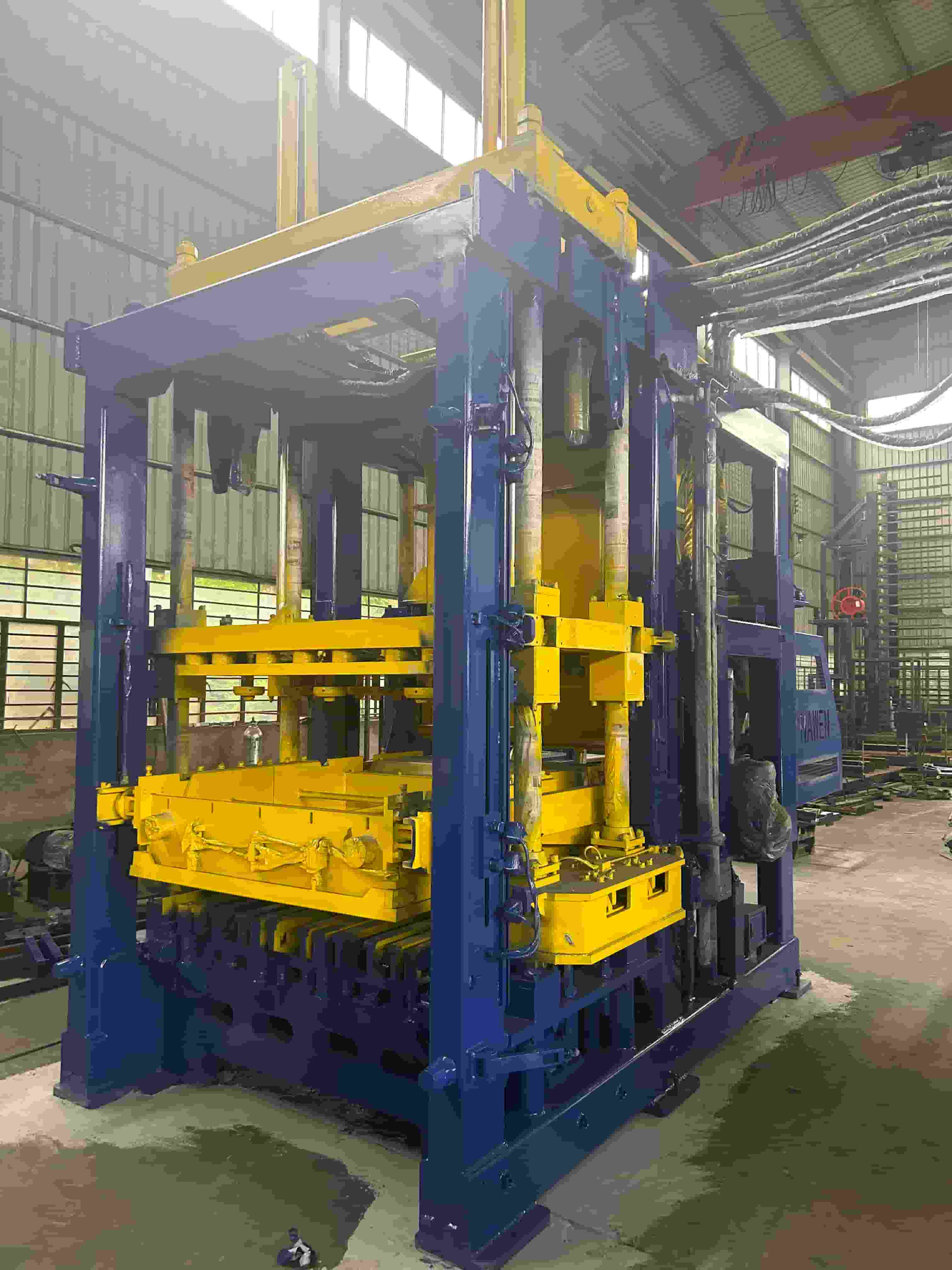
The first task of a foundation is to support the machine without unacceptable settlement. The second is to provide a stable geometric reference for installation. The third is to receive cyclic forces generated by the vibration system without developing harmful movement or resonance. These functions are related. A foundation that supports the static weight may still respond poorly to repetitive dynamic loading.
During forming, eccentric vibration produces rapidly changing forces. A well-designed machine directs useful vibration toward the mould and concrete mixture. The base and foundation must remain sufficiently stable so that energy is not wasted in uncontrolled frame or floor motion. This is particularly relevant for an industrial block making machine running thousands of cycles per shift. Small movement repeated many times can loosen a connection or enlarge an existing gap.
A poor base also complicates machine adjustment. Technicians may correct block height by changing vibration or pressure settings when the underlying problem is that the machine is no longer level or fully supported. Such parameter changes can hide the symptom temporarily and increase mechanical stress. Foundation level, support and anchoring should therefore be checked before repeated process adjustments are made.
Static and Dynamic Loads
Static loads include the machine's own mass and the weight of moulds, concrete, hoppers, hydraulic components and attached equipment. They determine bearing pressure and contribute to settlement. Dynamic loads arise from vibration, starting and stopping, moving assemblies and occasional abnormal events. Their magnitude, direction and frequency must be obtained from the equipment supplier rather than estimated only from motor power.
A foundation design also needs to consider load combinations. The heaviest mould may not be installed during initial commissioning, and a hopper may be full during normal operation. Conveyors or face-mix units can place additional loads on connected structures. The engineer should know which equipment is independently supported and which transfers forces through the main machine base.
Natural frequency matters because a foundation-soil system can respond strongly when excited near one of its own frequencies. More concrete mass alone does not guarantee an acceptable dynamic response. Foundation geometry, soil stiffness, embedment, damping and machine operating frequency all contribute. The local engineer should evaluate these parameters using the supplier's dynamic load data and the applicable design rules.
Do not rely on a general statement such as “the slab is thick enough.” A building floor designed for forklifts may have adequate static capacity but insufficient local rigidity or isolation for a vibropress. Conversely, an oversized isolated block can interfere with drainage, cable trenches or pallet transport if plant coordination occurs too late.
Information Required Before Design
Begin with the latest machine foundation drawing and installation manual. Confirm the exact model, pallet size, mould range, face-mix configuration and all accessories. Request base dimensions, machine mass, center of gravity where relevant, anchor locations, permitted anchor type, service openings and static and dynamic reactions. Verify drawing revision before issuing it for construction.
Next, obtain site information. A geotechnical investigation should describe soil layers, allowable bearing behavior, settlement characteristics, groundwater and any fill material. Newly filled industrial plots deserve particular attention because uneven compaction can produce differential settlement. Local climate may also influence drainage, frost protection or concrete construction practice.
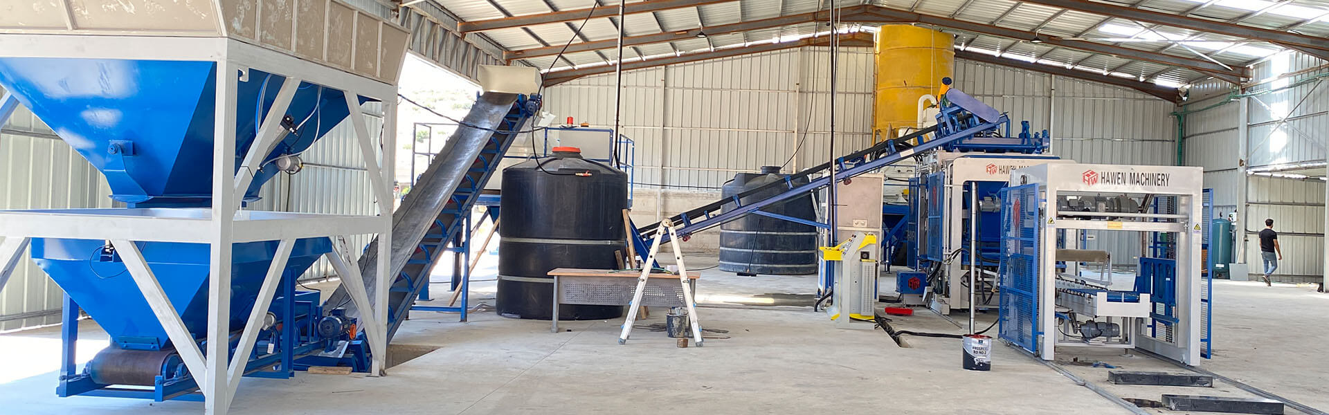
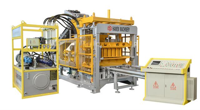
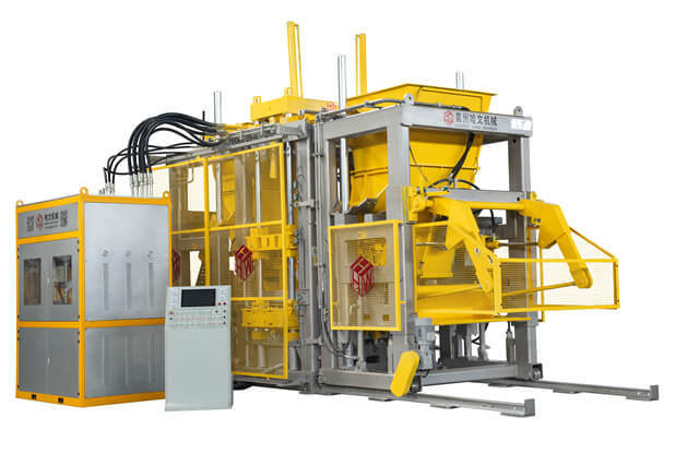
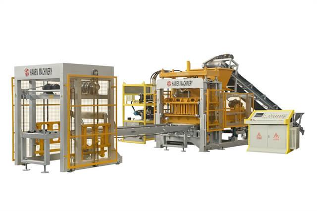
The layout must show more than the main machine footprint. Include the batching and mixing route, material conveyor, pallet provider, wet product conveyor, hydraulic station, electrical cabinet, maintenance access and lifting space. A complete QT10 production line, for example, includes equipment with different foundation and access needs. Align trenches and embedded items before pouring so that later cutting does not damage reinforcement.
Utilities should be coordinated at the same stage. Record electrical cable routes, hydraulic hose passages, water and drainage points, compressed-air pipes and grounding provisions. Keep service access open around components that require inspection. A foundation that physically supports the machine but blocks a filter, valve or removable motor creates long-term maintenance problems.
| Information source | Required information | Why it matters |
|---|
| Machine supplier | Loads, frequencies, base and anchor drawing | Defines equipment actions and interfaces |
| Geotechnical engineer | Soil profile, groundwater and settlement behavior | Determines ground response and foundation options |
| Plant designer | Line layout, trenches, traffic and maintenance zones | Prevents conflicts with production flow |
| Local engineer | Concrete, reinforcement, anchors and code checks | Produces a site-specific construction design |
Construction and Installation Control
Construction quality begins below the concrete. Excavate to the approved level, remove unsuitable material and prepare the subgrade as specified by the engineer. Confirm reinforcement position, concrete cover, embedded sleeves, anchor templates and construction joints before pouring. Photographs and inspection records are useful because these elements cannot be checked after concrete has hardened.
Anchor locations must match the machine drawing. A rigid template can maintain bolt spacing and verticality during the pour. If post-installed anchors are specified, drilling depth, hole cleaning, adhesive installation and curing should follow the engineered procedure. Moving an anchor hole or heating and bending a bolt on site can change its capacity and should not be treated as a routine adjustment.
Concrete needs adequate placement, consolidation and curing. Honeycombing around embedded items and weak laitance at the top surface reduce support quality. The machine should not be installed or operated until the foundation has reached the strength required by the project engineer. A visually dry surface does not demonstrate that the concrete is ready for dynamic loading.
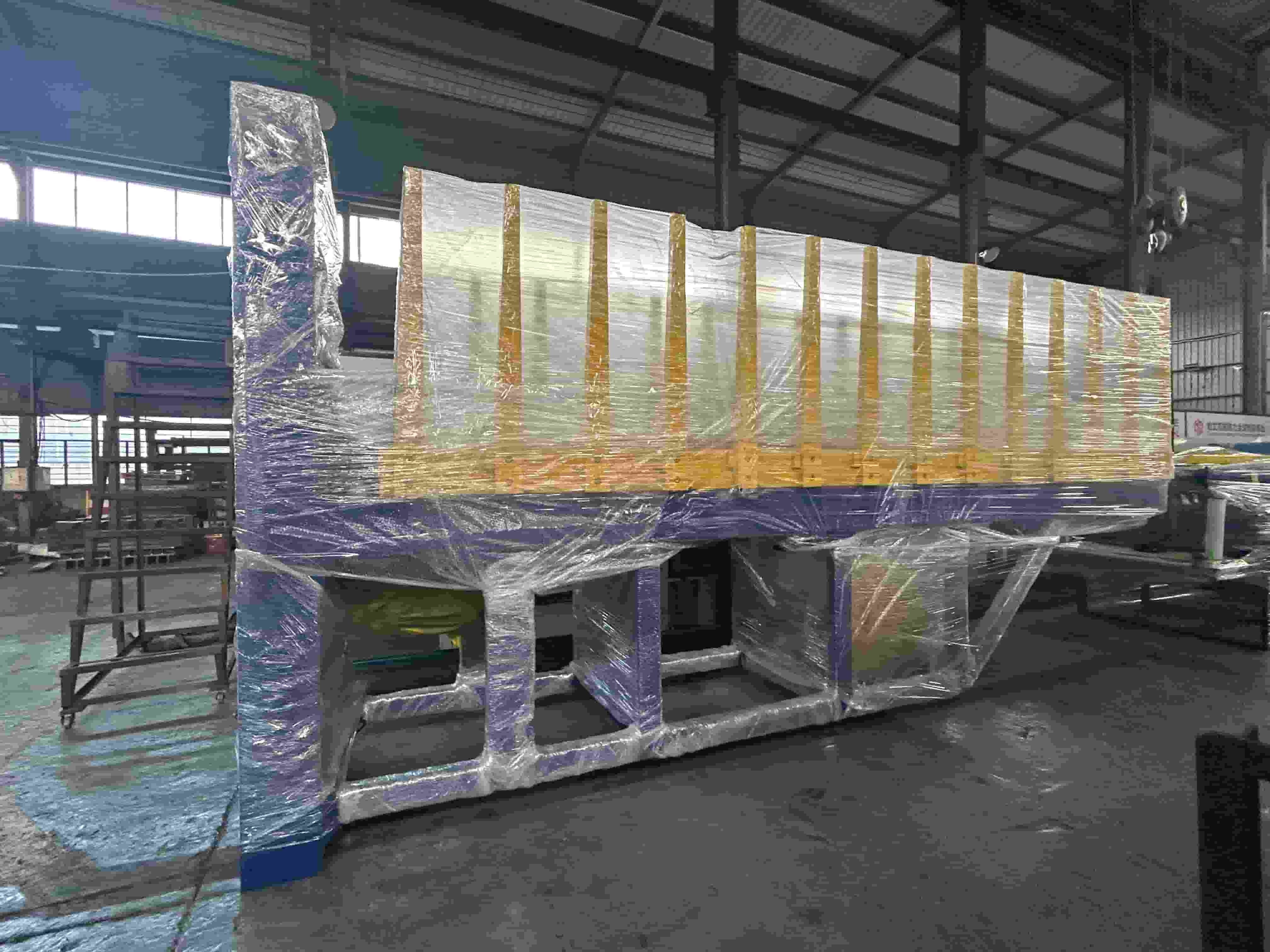
During installation, survey the reference elevations and centerlines. Use the leveling points defined by the supplier, then install shims or leveling devices according to the approved method. The base should receive continuous, sound support after grouting. Voids beneath the frame can create local movement and high contact stress. Grout preparation, placement and curing should follow the material supplier's instructions.
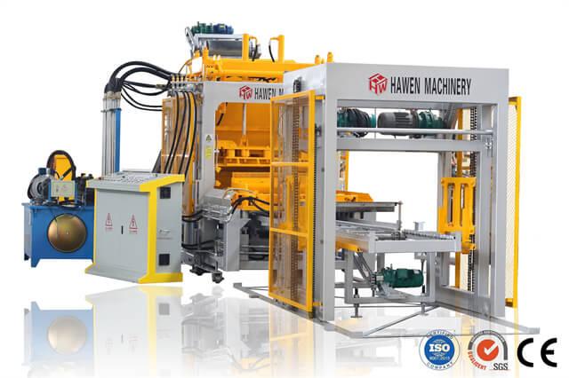
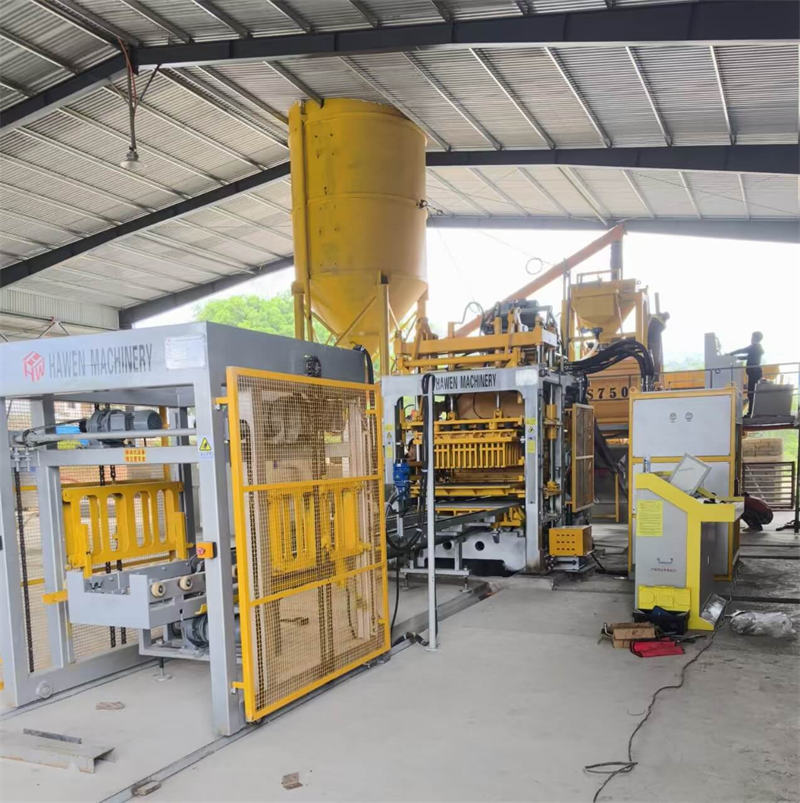
After alignment, tighten anchors in the required sequence and to the specified value. Recheck level and geometry because tightening can move the frame. Then connect conveyors and auxiliary equipment without forcing the main machine out of alignment. The installation examples in HAWEN's QT15 project case show why civil preparation and equipment positioning must be coordinated before full commissioning.
Vibration Isolation and Nearby Equipment
Isolation requirements depend on the machine and site. Some installations use a structurally separated foundation with a perimeter joint; others rely on a foundation designed as part of the floor system. Resilient materials or isolation devices should only be used where the machine supplier and engineer have designed for them. An arbitrary rubber layer beneath a machine can permit excessive movement, alter alignment and reduce anchor effectiveness.
Nearby sensitive equipment may include cement scales, laboratory instruments, electrical cabinets and office structures. Repeated floor vibration can disturb weighing signals, loosen terminals or make working conditions uncomfortable. Distance, separate support and correctly detailed joints can reduce transmission. Connected rigid pipes, cable trays and conveyors may bridge an isolation joint, so their flexibility and support need review.
Water management is also part of long-term stability. Washdown water should drain away instead of collecting around anchors or entering foundation joints. Standing water promotes corrosion and can carry cement fines into gaps. Outdoor or partially enclosed installations need suitable surface slopes and drainage that do not undermine the foundation edge.
During commissioning, measure or systematically observe vibration at the machine base and selected surrounding locations. Compare behavior across operating stages: empty movement, feeder operation, pre-vibration and main vibration. A repeated baseline helps maintenance teams identify gradual changes. Where vibration affects structures or personnel, use qualified measurement and evaluate it against the relevant local criteria.
Diagnosing Foundation-Related Problems
Possible signs include recurring anchor loosening, cracked grout, fretting marks beneath the base, widening joints, changing machine level and vibration that is much stronger on one side. Cracks in the surrounding floor may also appear, although not every floor crack proves that the machine foundation is defective. Record crack location and progression rather than drawing a conclusion from one observation.
When abnormal vibration develops, inspect the complete system. Worn vibration bearings, unbalanced eccentric settings, loose machine fasteners, a damaged mould or inconsistent material loading can generate similar symptoms. Check mechanical causes and foundation conditions together. HAWEN's guide to block machine operating instability provides a broader checklist for separating foundation symptoms from hydraulic, vibration and feeding faults. If anchors repeatedly loosen after correct tightening, investigate alignment, grout support and dynamic response instead of simply applying more torque.
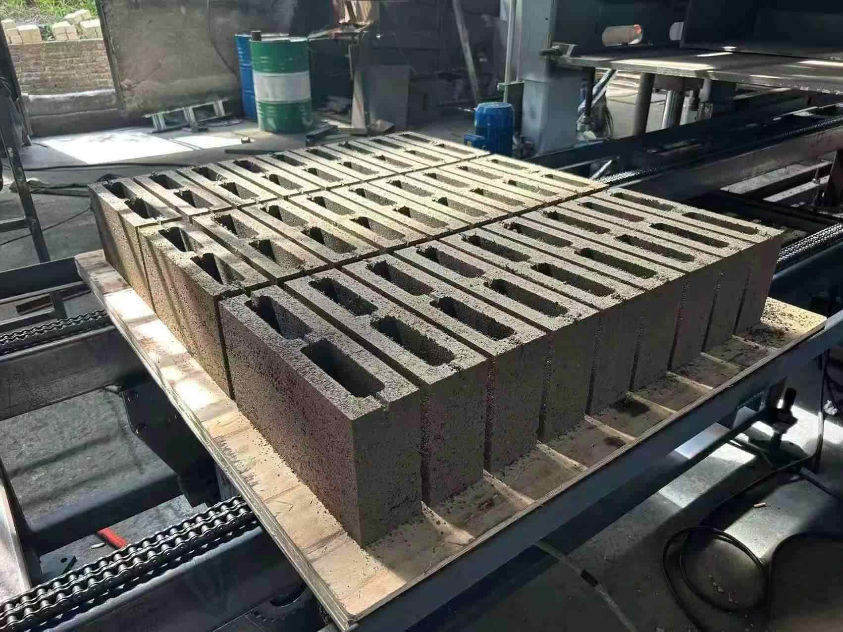
Block quality can provide supporting evidence. A gradual increase in height variation, one-sided compaction or shifting mould clearance may accompany foundation movement. Compare current survey measurements with commissioning records. Production data alone cannot locate the cause, but the combination of geometry, vibration observations and maintenance history can narrow the investigation.
Inspection and Maintenance
Create a baseline after final commissioning. Record machine level, anchor condition, grout edges, visible foundation surfaces and representative vibration observations. Mark survey points that can be measured consistently. Reinspect after the initial operating period and then at an interval based on production intensity and site conditions.
Keep the base clean enough to see leakage, corrosion and movement. Repair drainage problems promptly. Follow the supplier's anchor inspection method and do not retighten blindly while the machine is operating or under stored energy. If grout has separated or the foundation has settled, involve the equipment supplier and a structural professional before attempting a local patch.
Future changes require review. A heavier mould, face-mix unit, faster vibration setting or additional conveyor support may alter loads or interfaces. Likewise, adding a second production line close to the first can change vibration transmission through the floor. Check the foundation design before the plant makes a significant configuration change.
FAQ
Can the block machine be installed directly on an existing factory floor? Only after the floor, ground and dynamic loading have been checked for the specific machine. A floor suitable for normal traffic may not be suitable for forming vibration.
Does a heavier foundation always reduce vibration? Added mass can help in some designs, but soil stiffness, geometry and operating frequency also determine response. The complete system needs engineering evaluation.
Should rubber pads be placed under every block machine? No universal answer applies. Isolation elements must match the machine and anchor design; unplanned pads can allow harmful movement.
Why should machine level be recorded after commissioning? The baseline allows later measurements to identify settlement or movement that might otherwise be mistaken for a mould or process problem.
Conclusion
A stable block machine begins below the frame. Use current equipment loads, actual site data and a coordinated civil design; control anchors, level and grout during construction; and preserve baseline measurements for future inspection. This approach keeps vibration energy focused on forming concrete and supports consistent operation over the service life of the machine.





 Tel: +86-13905968794
 Email: export@hwmachines.com
 MP/WhatsApp: +86-13905968794
 Manufacturer Address:Nanan,Quanzhou City,Fujian Province,China