A concrete block mould drawing may look simple at first: a rectangular frame, several product cavities, a tamper head and a few mounting dimensions. For a production plant, however, the cavity layout shown on that drawing directly affects material filling, vibration distribution, mould rigidity, product quantity per cycle, demoulding behavior and ultimately the number of saleable blocks produced during each shift.
This is why approving a mould drawing should not be treated as an administrative step between quotation and manufacturing. The buyer needs to determine whether the proposed cavity arrangement actually matches the block machine, pallet, concrete mixture and finished-product requirements. A layout that maximizes the number of products on paper may create narrow feeding passages, insufficient steel between cavities or uneven compaction in real production.
The evaluation is particularly important for hollow blocks, interlocking pavers, kerbstones and special-shaped concrete products. Their moulds contain different combinations of cores, narrow webs, chamfers, shoulders, surface profiles and pressing areas. Each geometry changes the way semi-dry concrete moves inside the mould during filling and vibration.
Why cavity layout is a production decision, not just a drawing detail
Cavity layout describes how individual products are positioned within the available mould area. It determines the number of units produced during one forming cycle as well as the direction, spacing and orientation of those units.
For example, two mould designs may both fit on the same production pallet and form the same nominal paving stone. One arrangement may place products in straight rows, while another rotates selected cavities to increase pallet utilization. The second drawing may show a higher theoretical output, but it can also change material flow paths, tamper-head structure, mould-frame stiffness and the amount of steel separating adjacent cavities.
The correct question is therefore not simply, “How many blocks can fit on one pallet?” A better question is, “How many blocks can be filled, compacted, pressed and demoulded consistently on this machine without creating unacceptable production risk?”
A mould supplier normally needs to balance several competing requirements. Increasing cavity count raises theoretical pieces per cycle. Increasing cavity spacing usually improves structural support but reduces usable product area. Larger edge margins may strengthen the mould frame but reduce pallet utilization. Complex orientation may save space but make the tamper assembly and material distribution more difficult.
This balance is the reason cavity layout should be reviewed jointly with product geometry and machine information rather than approved from a block photograph alone.
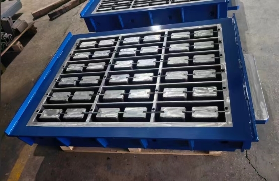
The production pallet establishes one of the main dimensional limits for cavity layout, but pallet dimensions and usable forming area are not necessarily identical. A pallet may measure a certain length and width while part of that surface must remain outside the effective product area because of mould-frame dimensions, machine guides, feeding requirements or mechanical clearances.
Before approving a mould drawing, buyers should confirm the actual pallet length, width and thickness used by the machine. The supplier should also understand the maximum mould size and effective forming area permitted by the machine structure.
The cavity arrangement should leave enough distance between the products and the outer mould frame. If products are positioned too close to the boundary, the remaining steel section may become difficult to support under repeated vibration and pressing. At the same time, excessive unused area reduces output without necessarily improving production quality.
Pallet orientation also matters. A 1400 × 1200 mm pallet, for example, does not automatically mean that a mould can simply be rotated by 90 degrees. Material-car travel direction, machine opening dimensions, tamper mounting and vibration-table arrangement may define which orientation is practical.
A useful drawing-review practice is to request dimensions for the complete cavity field rather than looking only at individual product size. The drawing should make it possible to understand the distance from the first cavity to the mould frame, spacing between adjacent cavities and total occupied forming area.
Cavity spacing, steel support and mould rigidity
The steel separating two neighbouring cavities performs a structural function. It must maintain geometry while the mould experiences repeated filling impact, vibration, pressing force and demoulding friction. Reducing this section only to gain another product position can increase stress in the mould assembly.
This consideration becomes more important for high-output moulds with many cavities. The centre region may contain multiple narrow steel partitions, while the external mould frame has considerably more support. The designer therefore needs to consider how the complete structure behaves rather than treating each cavity as an isolated shape.
Cavity spacing also influences cleaning and maintenance. Very restricted zones can trap concrete and make daily cleaning more difficult. Hardened concrete accumulation can interfere with mould movement, damage product edges and create misleading symptoms that operators may incorrectly attribute to moisture or hydraulic pressure.
For special-shaped paving stones, interlocking shoulders and curved profiles create additional local stress concentrations. Adequate support around these details helps the cavity maintain its intended geometry as the mould accumulates production cycles.
Buyers do not normally need to calculate mould stresses themselves. They should, however, ask why a particular spacing has been chosen when a supplier proposes an unusually dense cavity arrangement. A professional drawing discussion should explain the relationship between product count and structural feasibility rather than focusing only on maximum output.
Material feeding coverage across the mould
The feeding system must distribute semi-dry concrete across every cavity before final compaction. Cavity layout therefore has to be reviewed in relation to the direction and effective coverage of the material feeding car.
A common production risk occurs when the drawing uses nearly all available pallet area but places difficult-to-fill cavities near the extreme edges of the feeding zone. The mould may technically fit the machine while the material distribution becomes less repeatable between centre and outer cavities.
This does not mean outer cavities will automatically produce defective blocks. It means their filling performance should be considered during design and confirmed during testing.
Concrete for vibration-compacted blocks has relatively low workability compared with conventional cast concrete. It does not freely flow into every narrow space under gravity. The feeding system, material consistency and vibration sequence must encourage the mixture to enter the cavity uniformly.
If one cavity repeatedly produces a lighter product, weak corner or incomplete edge, the operator should map the defect according to its position on the pallet. A defect consistently appearing in the same mould location gives more diagnostic information than a general statement that “some blocks are weak.”
From an approval perspective, the buyer should review the cavity pattern together with feeding direction. For unusually shaped products, asking for a short explanation of expected material distribution before manufacturing can prevent a layout problem from becoming a production problem.
Hollow block webs, cores and narrow filling zones
Hollow blocks create a different cavity-layout challenge from solid paving products. The mould must accommodate external block walls, internal cores, narrow concrete webs and the mechanical structure supporting the core assembly.
A nominal 400 × 200 × 200 mm hollow block, for example, cannot be evaluated only by its outside dimensions. Hole configuration, shell thickness, internal web thickness, draft and core position all influence the mould structure and filling behavior.
The concrete needs to move around the cores and into relatively narrow sections before vibration and pressing are completed. If several hollow blocks are positioned very closely together, the designer still needs enough structural material around the cavities while maintaining reliable concrete distribution.
Core alignment is also important because internal geometry determines wall thickness and product weight distribution. If a core is incorrectly positioned, one wall may become thicker while another becomes thinner even though the external block dimensions remain acceptable.
When reviewing a hollow-block drawing, buyers should therefore examine the internal block geometry at the same level of attention as overall length and width. Wall thickness, core dimensions, core orientation and cavity quantity should all correspond to the intended finished product.
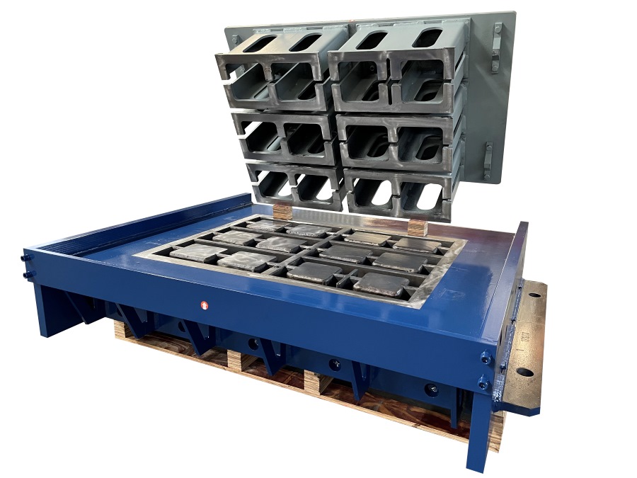
Paver orientation, edge geometry and surface consistency
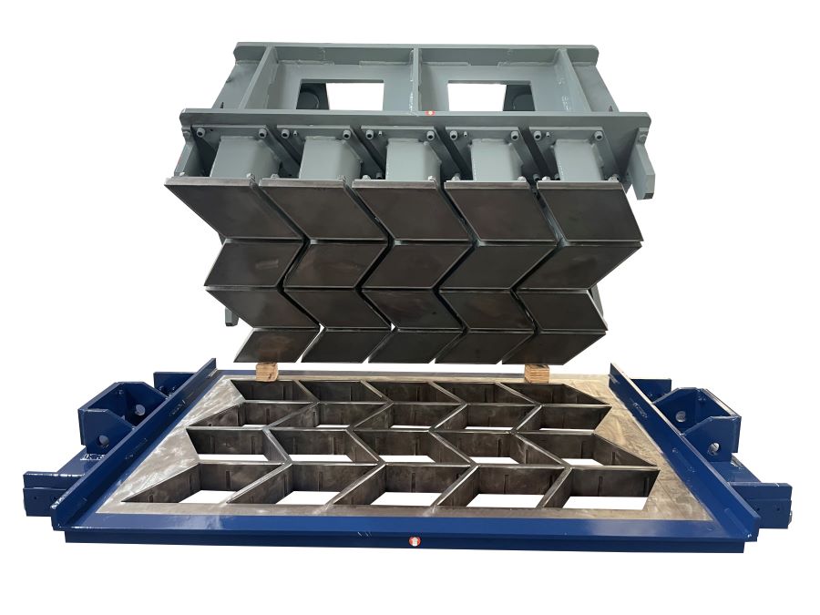
Interlocking paving stones often allow more cavity-layout options because smaller units can be rotated or nested within the available forming area. This flexibility can improve pallet utilization, but it also makes drawing approval more complex.
A paver may contain chamfers, spacer nibs, interlocking shoulders or narrow necks that must repeat accurately from cavity to cavity. The orientation of these features affects how the product fits into the overall mould layout and how much supporting steel remains between neighbouring profiles.
For pavers, dimensional consistency is closely connected with installation quality. Individual units are ultimately laid beside many other units. Small differences in interlocking geometry, spacer position or edge profile can accumulate across a paved surface.
The buyer should also review the tamper-head arrangement. The pressing shoes must correspond correctly with every cavity and maintain suitable clearance during movement. A dense paver layout can require a more complicated tamper assembly than a mould containing only several large hollow blocks.
If face-mix paving products are planned, surface appearance introduces another production variable. Material should reach each visible face consistently. Cavity arrangement, filling distribution, face-mix quantity and machine settings should therefore be evaluated as one system.
Why more pieces per cycle are not always better
Pieces per cycle is an important commercial figure because it contributes directly to theoretical hourly capacity. However, increasing product count produces economic value only when the additional units remain consistently saleable.
Theoretical output can be expressed simply as products per cycle multiplied by completed cycles per hour. Real plant output is more complicated because it is affected by stoppages, mould filling, material supply, product defects, cleaning, pallet movement, curing capacity and downstream handling.
A drawing that adds one additional row of products may therefore increase theoretical capacity while introducing slower feeding or greater sensitivity to material distribution. In that situation, the production advantage should be verified rather than assumed.
| Layout factor | Potential advantage | Risk to review | Buyer verification |
|---|
| Higher cavity count | More products per forming cycle | Reduced spacing, more complex filling and higher tamper complexity | Compare cavity count with machine forming area and trial-product consistency |
| Reduced edge margin | Better pallet utilization | Less structural support near the mould boundary | Confirm complete mould dimensions and frame design |
| Rotated product orientation | Additional products may fit on the pallet | Different feeding paths and more complicated tamper arrangement | Review feeding direction, shoe layout and cavity accessibility |
| Narrow cavity spacing | Higher density of products within the forming area | Wear, cleaning difficulty and reduced steel section | Ask how spacing is supported and how wear areas are maintained |
| Large product count | Higher theoretical hourly output | Uneven cavity mass or density can reduce saleable output | Sample products from different cavity positions during trial production |
For procurement decisions, saleable output is therefore a better concept than cavity count alone. Buyers should compare how reliably the mould can repeat product dimensions, weight, edges and surface quality across the entire pallet.
Drawing approval checklist for mould buyers
A mould drawing should be reviewed by people who understand both the finished product and the existing block machine. Where possible, production, maintenance and quality personnel should participate before the buyer signs the final approval.
Start with the product itself. Confirm overall dimensions, height, wall thickness, hole geometry, chamfers, interlocking features, spacer nibs, surface profile and any logo or special marking. Clearly distinguish critical dimensions from dimensions that are primarily manufacturing references.
Next, examine the cavity layout. Count the products manually rather than relying only on a written quantity. Confirm product orientation, spacing, distance to the outer frame and total occupied forming area.
Then review the machine interface. The mould must correspond with pallet dimensions, forming area, mould height, mounting positions, tamper connection, guide structure, feed-box movement and required demoulding travel.
Buyers purchasing a concrete block mould for an existing machine should provide the supplier with machine information and product requirements together. The required finished block cannot be separated from the mechanical interface that will form it.
The drawing revision also needs control. If dimensions or cavity arrangement change during technical discussion, the final approved revision should be clearly identified. Production should be based on that version rather than on an earlier drawing exchanged during quotation.
One practical observation from pre-shipment reviews is that overall photographs are not enough for mould acceptance. A buyer gains more useful information from views showing the cavity field, tamper shoes, mounting points and critical dimensional checks. When remote video inspection is used, the supplier should show details rather than only a short sequence of the mould opening and closing.
What to verify during trial production
Drawing approval confirms the intended design. Trial production confirms whether that design works together with the actual forming process.
During a material trial, do not inspect only the most visually attractive block from the pallet. Select units from different cavity positions. A practical pattern is to compare products formed near the feeding side, centre and opposite edge of the mould.
Record dimensions, green product mass where useful, edge condition, cavity formation, visible density and demoulding behavior. For hollow blocks, compare shell and web formation. For pavers, inspect corners, chamfers and interlocking details. When the mould contains many cavities, a position map can help connect repeated defects with a specific area.
If one location repeatedly produces a different result, the investigation should include cavity geometry, tamper shoe alignment, feeding distribution and local vibration behavior. If defects appear randomly throughout the pallet, the mixture, moisture, batching or operating settings may deserve more attention than the mould layout itself.
Trial production should also observe mould release. Products should separate without obvious dragging, repeated side damage or unstable movement. Clean demoulding does not prove every aspect of long-term mould performance, but it provides useful evidence that the selected geometry, concrete condition and machine movement are compatible.
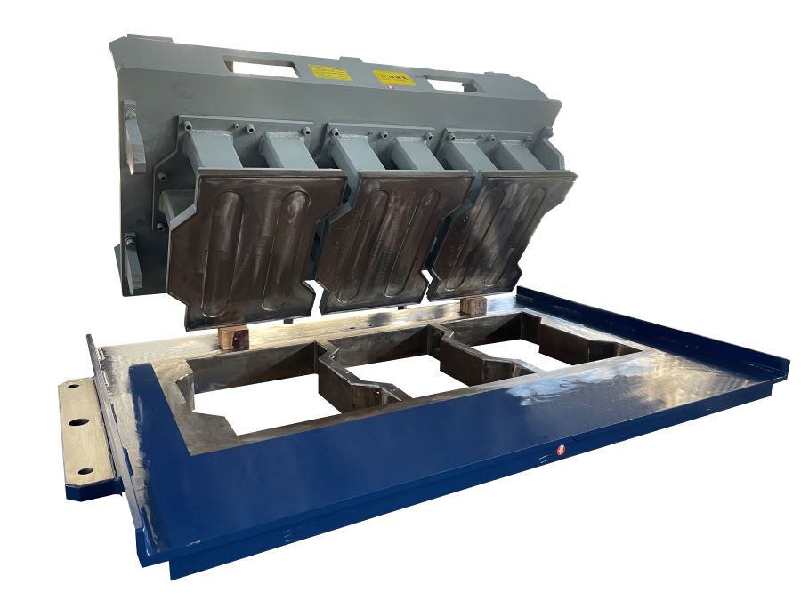
The trial should not be used to create unrealistic acceptance expectations. Fresh concrete products are affected by aggregate grading, moisture, cementitious materials, mixing, vibration, pressing and curing. A mould cannot compensate for an unstable mixture, just as excellent concrete cannot correct an incorrectly designed cavity.
The objective is to establish whether the cavity layout supports repeatable production under a controlled process.
FAQ
How is the number of cavities in a concrete block mould decided?
The number is determined by finished-product dimensions, pallet size, usable forming area, required spacing, mould structural design, feeding coverage and machine capability. It should not be calculated from pallet area alone.
Should I always choose the mould with the highest pieces per cycle?
No. A higher cavity count is useful only when the machine can fill, vibrate, press and demould every cavity consistently. Saleable output and process stability are more important than theoretical cavity count.
Why does spacing between mould cavities matter?
Spacing provides structural material between product cavities and influences mould rigidity, wear behavior, cleaning access and material distribution. Extremely narrow spacing may require additional engineering consideration.
What information should I check before approving a hollow block mould drawing?
Review external block dimensions, wall and web thickness, hole dimensions, core positions, cavity quantity, product orientation, pallet size, mould dimensions, mounting points, tamper connection and machine interface.
Can two block machines with the same pallet size use exactly the same mould?
Not necessarily. Pallet size is only one compatibility factor. Mould mounting, forming area, mould height, guide arrangement, feed system, tamper connection, vibration-table layout and demoulding stroke can differ between machines.
How can I check whether the cavity layout fills evenly?
During production trials, compare blocks from several cavity positions rather than checking only one sample. Record product mass, dimensions, corners, surface condition and filling quality. A defect that repeatedly follows one cavity position should be investigated separately from random defects.
Is a physical block sample enough for mould manufacturing?
A sample is useful for understanding geometry and appearance, but it should normally be supported by measured dimensions and a controlled drawing. Existing samples may already contain production variation or wear-related dimensional changes.
When should the buyer approve the final mould drawing?
Approval should take place after finished-product geometry, cavity count, machine interface, pallet information and important manufacturing requirements have been reviewed. The final drawing revision should then become the technical basis for manufacturing and inspection.
Conclusion
A concrete block mould cavity layout is not simply a geometric exercise for fitting the maximum possible number of products onto a pallet. It connects product design with material feeding, mould rigidity, vibration, pressing, demoulding and production economics.
Before approving a mould drawing, buyers should verify pallet and forming-area limits, cavity orientation, spacing, frame support, feeding coverage, hollow-block core geometry, paver edge details, tamper arrangement and machine connection points. Pieces per cycle should then be judged against expected production stability rather than treated as an isolated capacity figure.
The most useful final check is to connect the drawing with trial-production evidence. Samples from different cavity positions can reveal whether material distribution and product geometry remain consistent across the mould. Repeated position-specific differences should be investigated before regular production or shipment.
For a buyer comparing mould proposals, the next step is therefore to collect the finished-product drawing, actual machine information, pallet dimensions and required output, then review how each proposed cavity layout balances capacity with filling, structural support and repeatable product quality. This provides a more reliable basis for mould approval than price or maximum cavity count alone.





 Tel: +86-13905968794
 Email: export@hwmachines.com
 MP/WhatsApp: +86-13905968794
 Manufacturer Address:Nanan,Quanzhou City,Fujian Province,China