How to Reduce Thermal Bridging in Concrete Masonry Walls is a practical topic for buyers and plant managers who want a more stable block making machine workflow. The goal is not only to explain the issue, but to give a clear method that supports better output, cleaner operation, and stronger customer confidence.
In a professional concrete products factory, the block machine, material system, mold, pallet circulation, control system, and operator routine must work as one process. A good solution therefore looks at the whole line before changing one visible setting.
Thermal performance is evaluated for a specified wall assembly, not inferred from a machine model.
1. Understand where thermal bridges occur
A thermal bridge is a relatively conductive path that lets heat bypass a more insulating layer in the building envelope. In concrete masonry, webs can bridge insulated cores, while reinforced cells, floor slabs, shelf angles, lintels, and steel attachments create other paths. The result depends on the overall construction, not just nominal block width or an insulation label.
First decide what performance the project must meet. Energy codes and specifications may set assembly R-values, U-factors, or whole-building targets. Those values describe heat flow through the construction under defined assumptions. They are not interchangeable with the thermal resistance of a loose insulation product or a single unit. Confirm the adopted code, climate conditions, and reporting method with the project designer.
Thermal bridging can also affect interior surface temperatures and comfort. In some climates, a colder surface near a slab edge or metal connection may increase condensation risk. Evaluate temperature, humidity, air leakage, vapor movement, and drying potential together rather than treating thermal resistance as the only moisture-control measure.
2. Set a whole-assembly performance basis
Before comparing products, describe the envelope build-up: masonry wythe, unit density and geometry, grout locations, insulation type and position, finishes, air space, ties, and structural connections. Identify repeating conditions such as window jambs, parapets, floor lines, and roof intersections. A detail schedule distinguishes uninterrupted masonry-field performance from junction behavior.
Use a recognized method that accounts for heat flow through webs and repeating components. CMHA guidance identifies testing, isothermal-planes calculation, and two-dimensional analysis for masonry performance values. Select the method with the designer and use matching inputs. A center-of-cavity insulation value does not represent the complete construction.
Ask whether the target refers to uninterrupted-field performance or includes linear and point thermal bridges. A clear-field calculation may exclude slab edges or fasteners that matter to the building. The energy model or specification should state how those conditions are incorporated. This makes comparisons fair and helps the team decide whether it needs continuous insulation, revised details, or a different unit configuration.
Controlled product geometry supports reliable design inputs when a block is part of an insulated wall.
3. Map bypass paths before choosing an insulation strategy
Draw a continuous line around the conditioned space and trace where insulation is interrupted. Typical locations include concrete floor slabs passing the envelope plane, steel beams, columns, roof edges, balconies, window heads, and masonry shelf supports. Mark each bridge on elevations and sections. A coordination meeting between structural and envelope designers can reveal an interruption before it is hidden by finishes.
In single-wythe construction with insulation in unit cores, concrete webs and grouted cells can conduct heat around the insulation. A continuous layer on the interior or exterior can reduce this bypass, while a cavity assembly can place insulation between wythes. Reduced-web units may also help. Each strategy affects capacity, moisture behavior, attachment, fire detailing, and floor area, so compare the full specification.
A cavity does not automatically eliminate every bridge. Metal ties, shelf angles, fasteners, and opening details can still transfer heat. Specify tie layout, insulation returns, and structural transitions. Confirm the scope of proprietary details; a generic diagram is not construction-ready.
4. Choose a practical design response
Start with continuity. Keep insulation aligned across floor edges, roof lines, corners, and openings. Use details that avoid gaps and compression, and coordinate attachment points so they do not create unintended conductive paths. If insulation is split into layers, show how joints overlap and how moisture can drain or dry. Specify sequencing so installers can complete transitions before the next trade covers them.
For single-wythe construction, compare interior and exterior continuous insulation against core insulation in the context of climate, structure, and moisture management. Exterior insulation can keep masonry warmer and reduce bypass through webs; interior insulation may change the temperature profile and require careful air and vapor control. The correct choice depends on the assembly and local conditions, not a universal rule that one side is always safer.
Address linear bridges with project-specific thermal-break or insulation details where appropriate. A thermal break must be compatible with structural loads, fire requirements, water management, and long-term durability. Do not reduce reinforcement or alter grouted cells just to improve a thermal model without structural approval. Any change to the block geometry should be assessed against both performance evidence and the design loads it must resist.
The design team must account for webs, cores, grout, insulation, and junctions in whole-wall calculations.
5. Verify unit and insulation inputs
Use documented unit dimensions, density, aggregate type, web configuration, and grout locations in the calculation. Confirm whether published properties describe a unit, clear-field construction, or an assembly with specific insulation. If the production product differs from the model, send the actual drawing and material description to the designer. Small differences in web thickness or grouting can change the path in an analysis.
Specify insulation by product and installed condition. Record thickness, declared conductivity or resistance, facing, joint treatment, fasteners, and contact with adjacent materials. Verify that the selected value accounts for the design temperature and that the product is used within its approved application. Keep air barriers, water-resistive layers, and vapor-control layers distinct in drawings; one material does not automatically perform all these functions.
For concrete masonry, density affects thermal behavior as well as mass and other properties. If a project is considering lightweight aggregate or a different unit class, ask the engineering team to update the assembly calculation rather than copying values from another supplier's catalog. The concrete block manufacturer can provide product data, but the designer remains responsible for selecting the calculation inputs and confirming code compliance.
6. Control installation and field quality
Inspect insulation continuity before concealment. Check board joints, corner returns, slab-edge transitions, penetrations, attachment spacing, and compression around fasteners. Photograph representative details and note the location. Where multiple crews install different layers, assign a clear inspection hold point. Correcting a gap before cladding is complete is usually more straightforward than diagnosing a cold interior surface after occupancy.
Check air leakage as well as conductive paths. Air moving through cracks can carry heat and moisture. Seal the designated air-control layer around windows, doors, floor lines, and service entries. A blower-door test assesses whole-building airtightness; infrared imaging under suitable conditions can locate anomalies, but neither identifies every cause.
If field thermography reveals a cold strip, compare it with drawings, outdoor conditions, heating operation, wind, and indoor humidity. Rule out missing insulation, a structural bridge, air leakage, wet material, and thermal mass effects. Use targeted inspection before removing finishes. A visual temperature pattern is evidence to investigate, not a complete diagnosis or code determination.
7. Connect block production data with design coordination
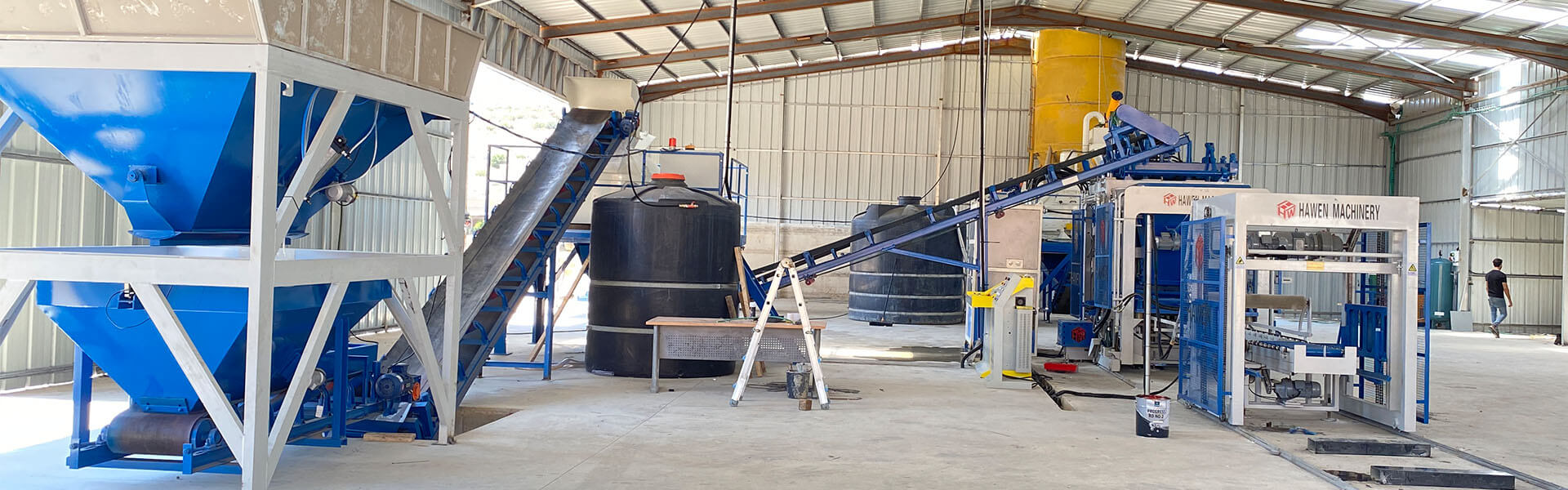
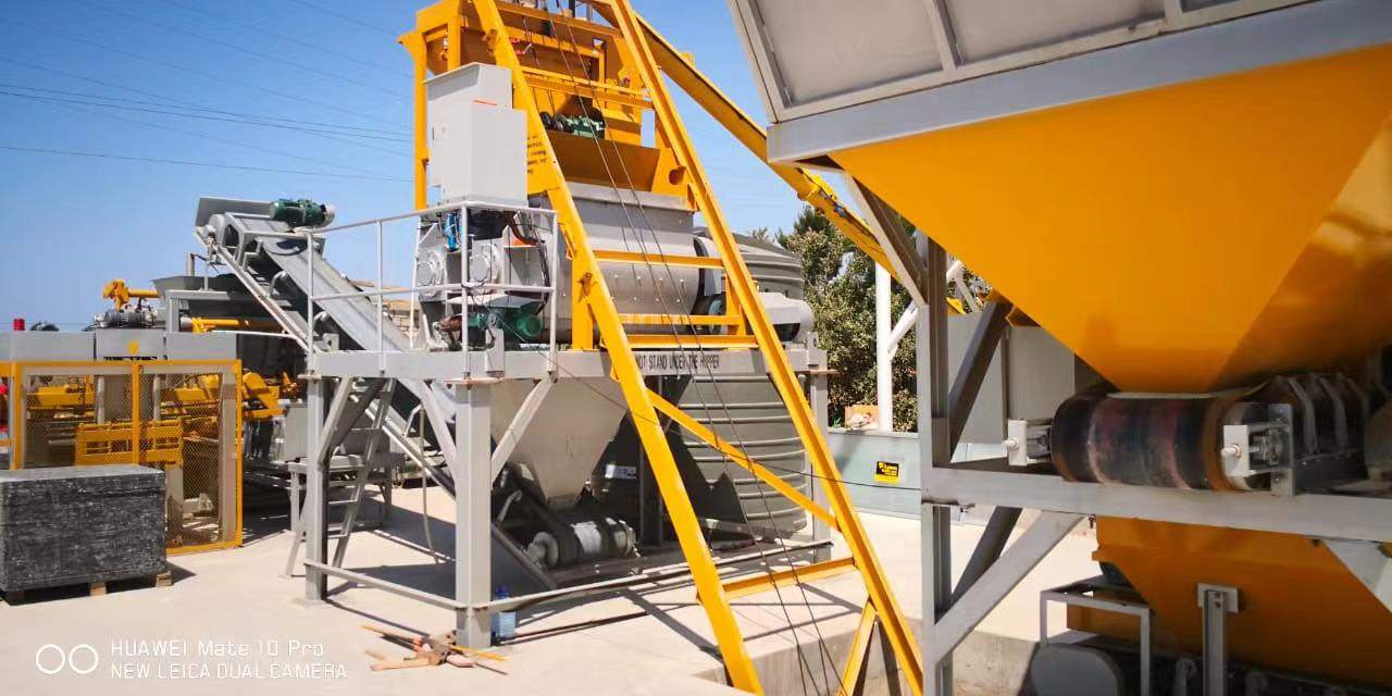
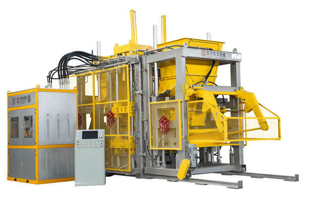
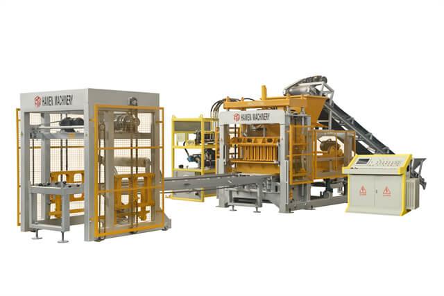
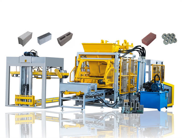
A brick machine or block machine contributes a repeatable product, but building thermal performance is determined after installation. Hawen Machinery can discuss the specified unit geometry, available molds, production capacity, pallet circulation, curing, and line configuration. Buyers should provide the intended product drawing and market requirements so the equipment proposal matches the units the design team expects to use.
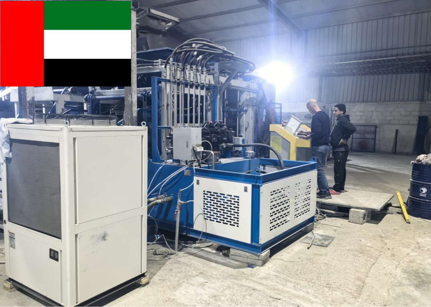
Hawen Machinery's four-shaft vibration box places eccentric blocks outside the housing to reduce internal resistance and support uniform compaction. Consistent compaction can help maintain the unit geometry specified for production; it does not certify an R-value or U-factor. Use dimensional checks and material records to make sure units supplied for a project match the data used in its assembly evaluation.
Before construction documents are issued, confirm that energy calculations, envelope sections, structural details, and product submittals use the same unit and insulation configuration. Resolve differences in core fill, density, attachment, and finish in writing. The reviewer should be able to follow assumptions from the code target to the modeled construction and then to the material delivered to the site.
During construction, log deviations and obtain approval before accepting substitutions. If a changed block, insulation, tie, or connection affects heat flow, ask the design team to revise the analysis. Keep product labels, delivery records, inspection photographs, and any field-test results with the closeout documents. This makes future maintenance and retrofit decisions more reliable.
CMHA's technical references on thermal bridges and single-wythe masonry R-values explain why webs and junctions matter. They are useful background, not a replacement for the locally adopted code or a project-specific design. The practical solution is a coordinated envelope whose calculated performance matches details crews can build and inspect.
Action checklist
Define the required assembly R-value or U-factor and the code-approved calculation or test method.
Map webs, grouted cells, slab edges, steel, lintels, ties, and opening transitions as potential heat-flow paths.
Coordinate continuous insulation, air control, vapor strategy, water drainage, fire detailing, and structural loads.
Use actual unit density, geometry, grout pattern, and insulation product data in the assembly calculation.
Inspect insulation continuity and air sealing before concealment; investigate field anomalies before repair.
Record approved product revisions, substitutions, calculations, and installation checks for project closeout.
Thermal performance improves when the design team treats the wall as a continuous system rather than a stack of isolated product values. Trace every bypass, keep insulation and air control continuous, and verify the details that connect masonry to the rest of the building. That rigor makes energy targets more credible, interiors more comfortable, and the finished concrete masonry wall easier to maintain.
FAQ
What is the most common thermal bridge in a concrete masonry wall? Concrete webs, grouted cells, slab edges, steel supports, and discontinuities around openings can all form bridges; the dominant path depends on the wall design.
Can insulation in block cores eliminate thermal bridging? Not necessarily. Concrete webs and grouted cells may bypass core insulation, so use a whole-assembly calculation that represents the actual configuration.
Is continuous insulation always the right solution? It can reduce bypass paths, but placement must also suit structure, climate, moisture control, fire requirements, and local code.
Can I use a block's catalog R-value for the whole wall? Only if the value clearly represents the specified assembly and method. A unit or center-of-cavity value may not include bridges and junctions.
Does lightweight concrete block improve wall insulation? Lower density can affect thermal properties, but the designer should compare the full assembly and verify structural and code requirements.
Can infrared imaging prove a wall meets its energy target? No. Thermography can identify temperature patterns under suitable conditions; it does not replace a recognized calculation, test, or code review.
What can Hawen Machinery contribute to a thermal-wall project? Hawen can discuss the required unit geometry, molds, machine configuration, and production controls; the design professional evaluates the installed wall's thermal performance.






 Tel: +86-13905968794
 Email: export@hwmachines.com
 MP/WhatsApp: +86-13905968794
 Manufacturer Address:Nanan,Quanzhou City,Fujian Province,China